Rear view
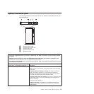
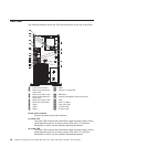
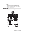
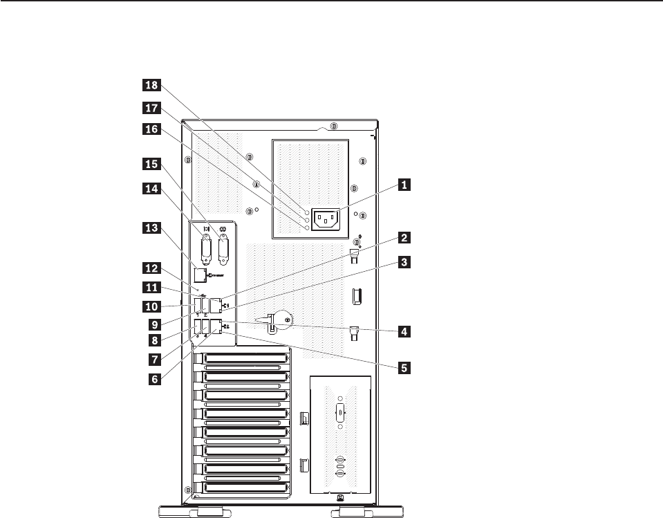
The following illustration shows the LEDs and connectors on the rear of the server.
1 Power cord connector 10 USB 1
2 Ethernet transmit/receive
activity LED
11 Ethernet 1 10/100/1000
3 Ethernet link status LED 12 NMI button
4 Ethernet transmit/receive
activity LED
13 Systems-management Ethernet connector
5 Ethernet link status LED 14 Video
6 Ethernet 2 10/100/1000 15 Serial 1 (COM 1)
7 USB 4 16 Fault (error) LED
8 USB 3 17 ac power LED
9 USB 2 18 dc power LED
Power-cord connector
Connect the power cord to this connector.
ac power LED
This green LED provides status information about the power supply. During
typical operation, both the ac and dc power LEDs are lit. For any other
combination of LEDs, see the Hardware Maintenance Manual.
dc power LED
This green LED provides status information about the power supply. During
typical operation, both the ac and dc power LEDs are lit. For any other
combination of LEDs, see the Hardware Maintenance Manual.
26 ThinkServer TD200 Types 3724, 3808, 3809, 3815, 3817, 3824, 3826, 3836: Installation and User Guide


