


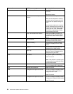
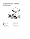
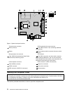
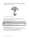
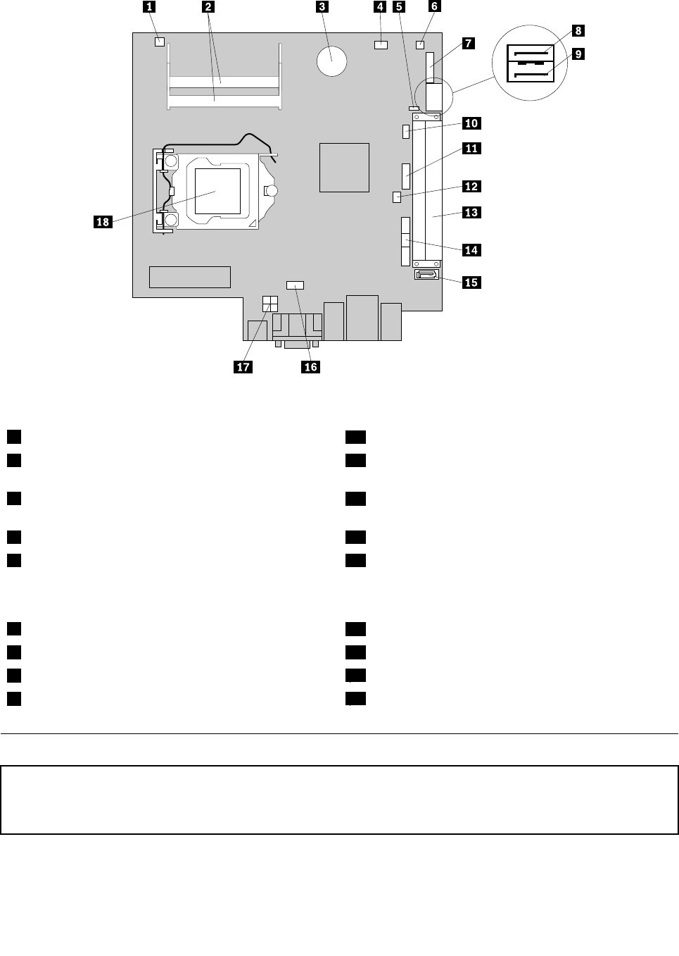
Figure 4. System board part locations
1 Thermal sensor connector
10 PS/2 keyboard and mouse connector
2 Memory slots (2) 11 Front USB connector 2 (for connecting additional
USB devices)
3 Battery
12 Cover presence switch connector (Intrusion switch
connector)
4 Microprocessor fan connector
13 PCI card slot
5 Clear CMOS (Complementary Metal Oxide
Semiconductor) /Recovery jumper
14 Front USB, front panel, and front audio connector
(for connecting USB ports 1 and 2 on the front bezel,
LED indicators and power switch, and microphone and
headphone connectors on the front bezel)
6 Internal speaker connector
15 SATA connector 1 (SATA 3.0 connector)
7 Serial (COM2) connector 16 System fan connector
8 eSATA connector
17 4-pin power connector
9 SATA connector 2 (SATA 2.0 connector)
18 Microprocessor
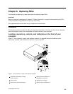
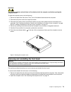
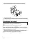
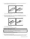
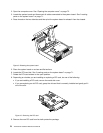
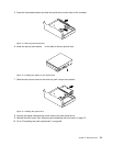
Opening the computer cover
Attention:
Do not open your computer or attempt any repair before reading and understanding the “Important safety information”
in the ThinkCentre User Guide. To obtain a copy of the ThinkCentre User Guide, go to:
http://www.lenovo.com/ThinkCentreUserGuides
This section provides instructions on how to open the computer cover.
72 ThinkCentre Hardware Maintenance Manual