


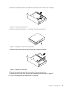
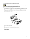
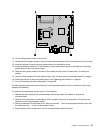

10. Lift the failing system board off the cover.
11. Position the new system board so that the screw holes are aligned with the mounting studs on the cover.
12. Install the screws to secure the new system board to the protective cover.
13. Install the memory modules, PCI card, battery, and microprocessor that you removed from the failing
system board to the new system board.
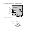
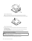
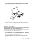
14. Slide the new system board to the rear of the chassis and then pivot it inward until it is locked into
position.
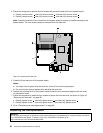
15. Connect all the cables to the new system board. See “Locating parts on the system board” on page 71.
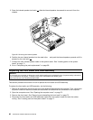
16. Install the heat sink to the new system board. See “Replacing the heat sink” on page 81.
17. Go to “Completing the parts replacement” on page 98.
The failing system board must be returned with a microprocessor socket cover to protect the pins during
shipping and handling.
To install the microprocessor socket cover, do the following:
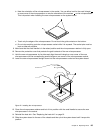
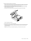
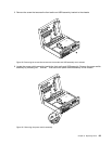
1. Release the lever securing the microprocessor retainer and open the retainer to access the
microprocessor.
2. Grasp the microprocessor on the sides and lift it straight up and out of the socket. Do not touch the
contacts on the microprocessor socket.
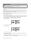
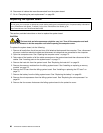
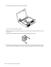
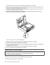
3. Note the orientation of the socket cover. Align the notches 1 of the microprocessor socket cover with
the alignment keys 2 of the microprocessor socket.
4. Install one side of the socket cover into the microprocessor socket as shown.
Chapter 8. Replacing FRUs 87