


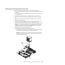
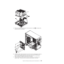
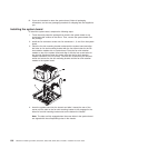
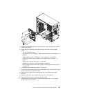
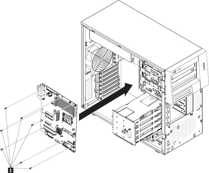
5. Install the eight screws (seven in front and one in rear) that secure the system
board to the chassis.
6. Install any of the following components that you removed from the system
board:
v The fan connector covers.
v Hypervisor key (see “Installing a USB embedded hypervisor flash device” on
page 61).
v Virtual media key (see “Installing the virtual media key” on page 63).
v SAS/SATA controller (see “Installing a ServeRAID BR10-il controller” on
page 91 ).
v Battery (see “Installing the battery” on page 89).
v DIMMs (see “Installing a memory module” on page 38).
v Microprocessor and fan sink (see “Installing a microprocessor and fan sink”
on page 101).
v Adapters (see “Installing an adapter” on page 57).
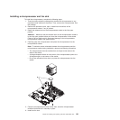
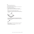
7. Press and hold the retaining tab on top of the cage; then, rotate the drive cage
into the chassis until it locks into place.
8. Reconnect any cables to the system board that you disconnected during
removal.
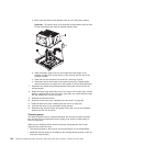
9. Install the side cover (see “Installing the side cover” on page 33).
10. Lock the side cover if you unlocked it during removal.
11. Reconnect the external cables and power cords; then, turn on the attached
devices and turn on the server.
Chapter 6. Installing and replacing customer replaceable units 107