


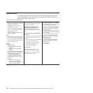
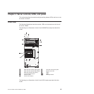
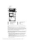
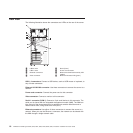
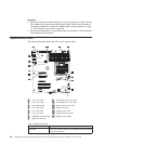
Rear view
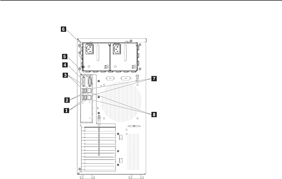
The following illustration shows the connectors and LEDs on the rear of the server.
1 USB 3 and 4 5 Serial (Com1)
2 USB 1 and 2 6 Power cord connector
3 Ethernet connectors 7 Ethernet transmit/receive activity LED
(amber)
4 Video connector 8 Ethernet link status LED (green)
USB 1-4 connectors: Connect a USB device, such as USB mouse or keyboard, to
any of these connectors.
Ethernet 10/100/1000 connector: Use these connectors to connect the server to a
network.
Power-cord connector: Connect the power cord to this connector.
Video connector: Connect a monitor to this connector.
Serial 1 connector (COM 1): Connect a 9-pin serial device to this connector. The
serial port is shared with the integrated management module (IMM). The IMM can
take control of the shared serial port to perform text console redirection and to
redirect serial traffic, using Serial over LAN (SOL).
Ethernet connectors: Use either of these connectors to connect the server to a
network. When you use the Ethernet 1 connector, the network can be shared with
the IMM through a single network cable.
18 ThinkServer TS200 Types 6522, 6523, 6524, 6525, 6526, 6528, 6529, and 6530: Installation and User Guide