


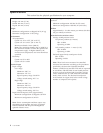
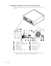
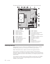
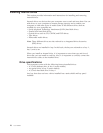

The following illustration shows the locations of parts on the system board.
1 12v power connector 13 SATA 2 connector
2 Diskette drive connector 14 SATA 1 connector
3 Speaker connector 15 Cover presence switch connector
4 Memory connector 4 16 Power supply connector
5 Memory connector 3 17 PCI Express (x16) graphics adapter
connector
6 Memory connector 2 18 PCI Express (x1) adapter connector
7 Memory connector 1 19 PCI adapter connector 2
8 Clear CMOS/Recovery jumper 20 PCI adapter connector 1
9 Front panel connector 21 Battery
10 PATA IDE connector 22 Microprocessor
11 SATA 4 connector 23 Microprocessor fan connector
12 SATA 3 connector 24 Microprocessor heat sink
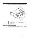
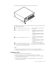
Installing memory
Your computer has four connectors for installing dual inline memory modules
(DIMMs) that provide up to a maximum of 4.0 GB of system memory.
Note: Addressable memory might be less than total supported memory.
System memory is divided into two channels (channel A and B). Memory
connectors 1 and 2 are channel A, and memory connectors 3 and 4 are channel B.
If memory modules are present in both channels, your computer operates in dual
channel mode.
Your computer has either double data rate (DDR) or double data rate 2 (DDR2)
memory. The type of memory required depends on the system board that is
installed in your computer.
12 User Guide