


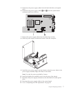
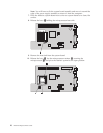
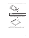
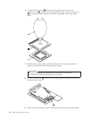

14. Use the vacuum pen 1 to lower the microprocessor straight down into the
microprocessor socket.
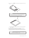
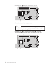
15. Lower the microprocessor retainer and secure it with the lever.
Note: There will be a black plastic cover on the microprocessor retainer to
protect the socket on the new system board. When you lock the
microprocessor in position, remove the black plastic cover. Place the black
plastic cover on the microprocessor retainer of the defective system board.
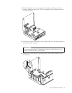
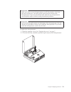
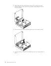
16. Install and secure the heat sink on the microprocessor.
17. Remove the memory modules from the defective system board, and install
them on the new system board. See to “Replacing a memory module” on page
17. Return here after installing the memory modules and continue to the next
step.
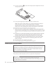
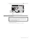
18. Install the new system board assembly into the computer chassis by aligning
the tabs on the rear of the system board with the slots in the rear of the
computer chassis. Slide the system board toward the rear of the chassis.
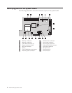
19. Reconnect the cables that were disconnected from the system board. Make
sure all cables are routed correctly. See “Identifying parts on the system
board” on page 4.
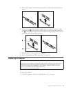
20. Reinstall the PCI riser assembly and adapters.
21. Go to “Completing the CRU replacement” on page 28.
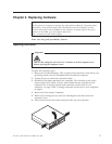
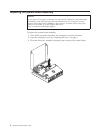
Replacing the microprocessor
Attention
Do not open your computer or attempt any repair before reading the “Important safety
information” in the Quick Reference that was included with your computer or in the
Hardware Maintenance Manual (HMM) for the computer. To obtain copies of the Quick
Reference or the HMM, go to the Support Web site at
http://www.lenovo.com/think/support.
This section provides instructions on how to replace the microprocessor.
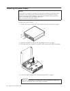
Important
Turn off your computer for at least one hour before removing the
microprocessor to allow the thermal interface between the microprocessor and
the heat sink time to cool down.
12 Hardware Replacement Guide