


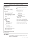
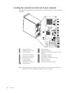
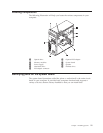
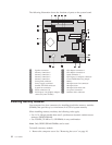
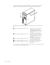

The following illustration shows the locations of parts on the system board.
1 Speaker connector 12 PCI adapter connector 1
2 Memory connector 4 13 PCI adapter connector 2
3 Memory connector 3 14 Serial connector 2
4 Memory connector 2 15 PCI Express x1 adapter connector
5 Memory connector 1 16 Clear CMOS/Recovery jumper
6 Front panel connector 17 Battery
7 Power supply connector 18 Microprocessor fan connector
8 Parallel ATA IDE connector 19 Microprocessor
9 System fan connector 20 Microprocessor heat sink
10 SATA connectors (4) 21 12v power connector
11 PCI Express x16 graphics adapter
connector (some models)
22 Diskette drive connector
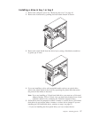
Installing memory modules
Your computer has four connectors for installing dual inline memory modules
(DIMMs) that provide up to a maximum of 4.0 GB of system memory.
When installing memory modules, the following rules apply:
v Use 1.8 V, 240-pin, double data rate 2 synchronous dynamic random access
memory (DDR2 SDRAM).
v Use 256 MB, 512 MB or 1.0 GB DIMMs in any combination.
Note:
Only DDR2 SDRAM DIMMs can be used.
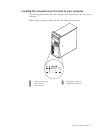
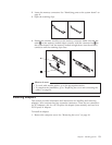
To install a memory module:
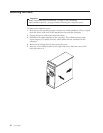
1. Remove the computer cover. See “Removing the cover” on page 10.
12 User Guide