


66
Lenovo IdeaPad U300/U300s/U400 Hardware Maintenance Manual
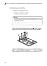
1080 LCD unit (U300s)
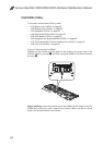
For access, remove these FRUs in order:
• “1010 Base cover (U300s)” on page 54
• “1020 Battery pack (U300s)” on page 56
• “1030 Speakers (U300s)” on page 57
• “1040 Solid State Disk (U300s)” on page 58
• “1050 USB Board (U300s)” on page 59
• “1060 Keyboard and keyboard bezel (U300s)” on page 60
• “1070 PCI Express Mini Card for wireless LAN (U300s)” on page 64
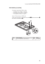
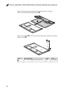
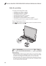
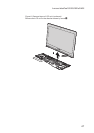
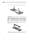
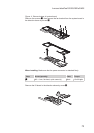
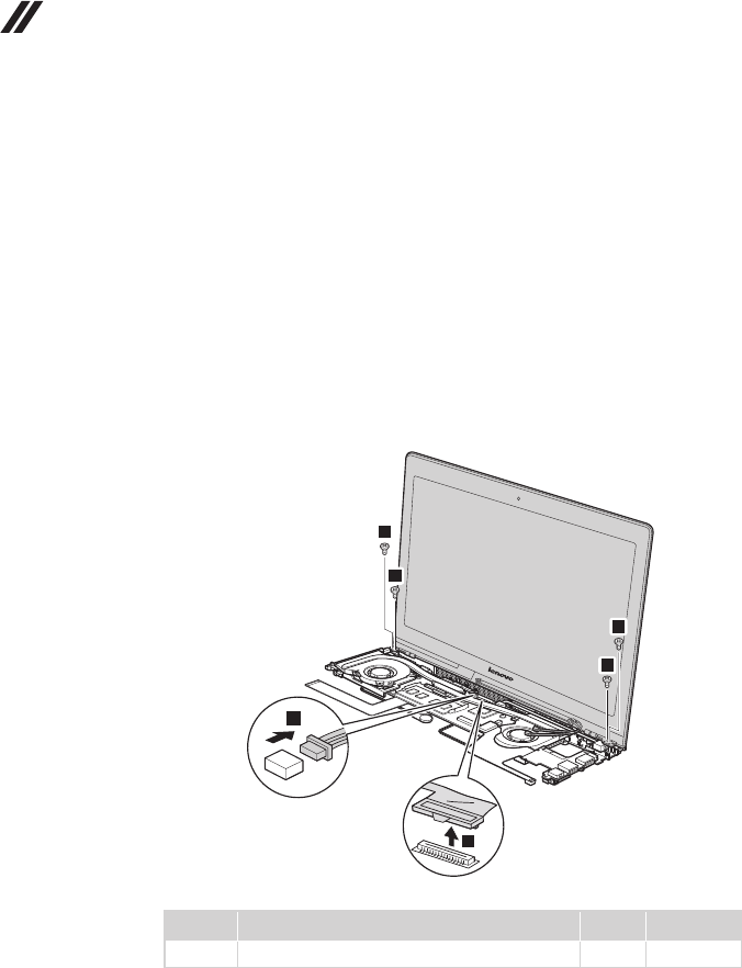
Figure 8. Removal steps of LCD unit
Unplug the LCD connector and the camera connector in the direction shown by
arrows
1
2
. Remove four screws
3
.
U300s
1
2
3
3
3
3
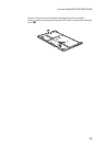
Step Screw (quantity) Color Torque
3
M2.5 × 4 mm, at-head, nylok-coated (4) Black 2.5 ± 0.2 kgfcm
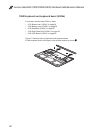
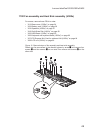
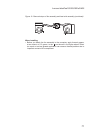
When installing:
Route the antenna cables along the cable guides. As you route the cables, •
make sure that they are not subjected to any tension. Tension could cause
the cables to be damaged by the cable guides, or a wire to be broken.
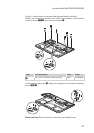
Make sure that the LCD connector is attached rmly and make sure that you •
do not pinch the antenna cables when you attach the LCD assembly. Route
the LCD cable along the cable guides.