


81
Lenovo IdeaPad U300/U300s/U400
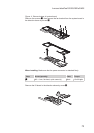
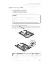
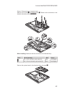
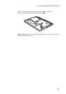
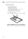
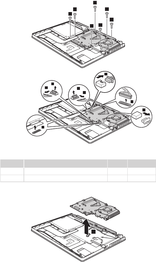
Figure 5. Removal steps of system board
Remove four screws
1
and three screws
2
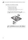
. Detach seven connectors in the
direction shown by arrows
3
4
5
6
.
1
1
1
2
1
2
2
6
4
5
6
3
4
4
3
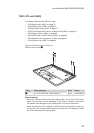
When installing: Make sure that the connectors are attached rmly.
Step Screw (quantity) Color Torque
1
M2 × 6 mm, at-head, nylok-coated (4) Black 1.6 ± 0.24 kgfcm
2
M2 × 2.5 mm, at-head, nylok-coated (3) Black 1.6 ± 0.24 kgfcm
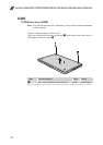
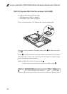
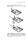
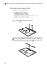
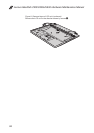
Remove the system board in the direction shown by arrow
7
.
7