


70
Lenovo IdeaPad U300/U300s/U400 Hardware Maintenance Manual
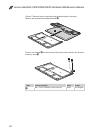
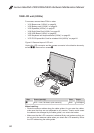
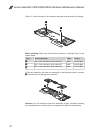
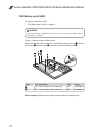
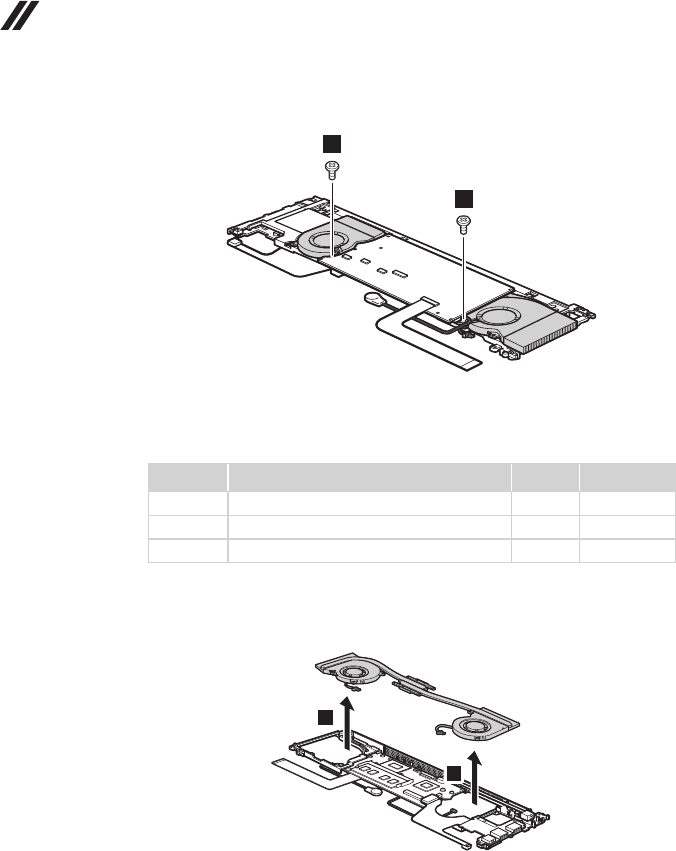
Figure 10. Removal steps of fan assembly and heat sink assembly (continued)
4
4
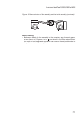
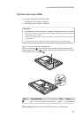
When installing: Make sure that the fan connector is attached firmly to the
system board.
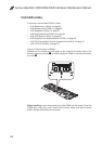
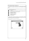
Step Screw (quantity) Color Torque
2
M2 × 4 mm, at-head, nylok-coated (4) White 1.5 ± 0.2 kgfcm
3
M2 × 3 mm, at-head, nylok-coated (4) White 1.5 ± 0.2 kgfcm
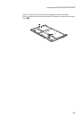
4
M2 × 3 mm, at-head, nylok-coated (2) White 1.5 ± 0.2 kgfcm
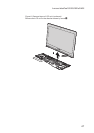
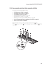
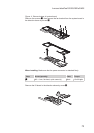
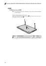
Lift the fan assembly and heat sink assembly in the direction shown by arrows
5
. Be careful not to damage the connector.
5
5
Attention: Do not handle the heat sink assembly roughly. Improper handling
can cause distortion or deformation and imperfect contact with components.