


T
WISTED
-P
AIR
D
EVICES
4-3
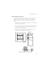
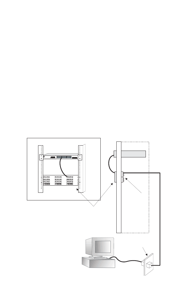
Network Wiring Connections
Today, the punch-down block is an integral part of many of the newer
equipment racks. It is actually part of the patch panel. Instructions for
making connections in the wiring closet with this type of equipment
follows.
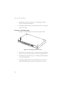
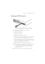
1. Attach one end of a patch cable to an available port on the switch, and
the other end to the patch panel.
2. If not already in place, attach one end of a cable segment to the back
of the patch panel where the punch-down block is located, and the
other end to a modular wall outlet.
3. Label the cables to simplify future troubleshooting. See “Cable
Labeling and Connection Records” on page 4-8.
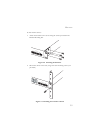
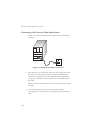
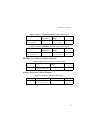
Figure 4-2 Wiring Closet Connections
Equipment Rack
(side view)
Network Switch
Patch Panel
Punch-Down Block
Wall
witch10/100
6724L3
E
S
4
5
2
4
C
12
78
12
3
4
5
6910
11
13
14
15 16
17
18 19
20
2122
23
24
Link/Act
Link/Act
Power
1000
1000
1234
13141516
5
678
17181920
9101112
21222324
21 22
23
24
o n e
level
GSW-247624PortGigabitw4PortSFPWeb SmartSwitch-/-
SharedSFPPort