and Specifications
Installation and
Safety Guidelines
Installation, Wiring,
2–4
Installation, Wiring, and Specifications
Power Wiring
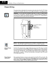
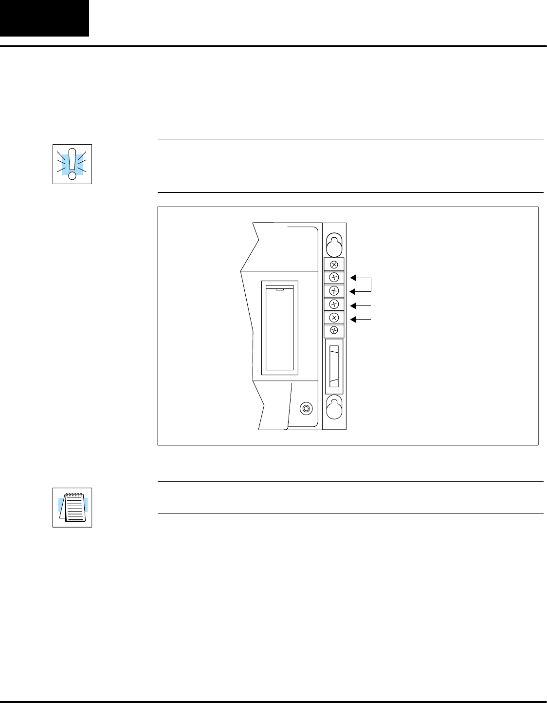
The power wiring is attached to the terminals on the right side of the D4–470. Follow
the legend on the upper right corner of the hinged lid as shown in the diagram below.
WARNING: Do not strip wire insulation more than 8–10mm, or approximately
0.3875 inches. Use spade or ring lugs if possible. Exposed conductors longer than
this length could make contact with the metal case of the D4–470. Contact between
the conductors and the case could be hazardous.
100-120/200-240VAC~
50/60Hz
Logic Ground
Chassis Ground
NOTE: We recommend including an on–off switch in the power circuit of the
D4–470. This will make it easier to cycle power to the unit when necessary.
The D4–470’s internal power supply distributes power to the CPU–board, the CPU
fan, the hard disk drive, and the floppy disk drive. Additional power is also available
to power the expansion slots. Three voltages are provided to power internal devices:
+5, +12, and –12 VDC. You will find the current limits for each voltage in the
specifications on page 2–7. Be sure the total power consumption does not exceed
the available power limits.
Many peripheral devices consume more power than the D4–470 can furnish. We
recommend that you do not attempt to power external devices using the internal
power supply. Do not attempt to power a CD–ROM drive using the D4–470’s
internal power supply. Use an external power source.
Internal Power
Supply
Power Supply
Limitations


