Accessories
Installation and
Safety Guidelines
Installing Hardware
3–2
Installing Hardware Accessories
Adding Third–Party Boards to Expansion Slots
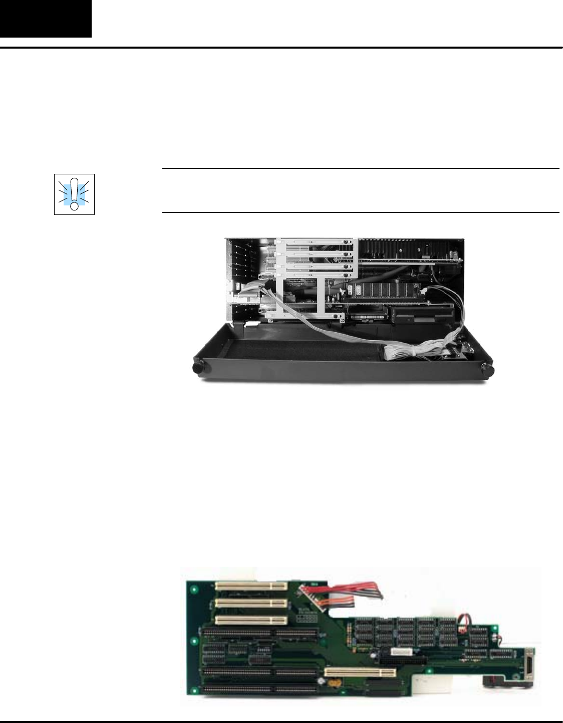
Loosen the two thumb screws on the hinged lid of the D4–470 to open the lid and
expose the interior of the case. The compartment is compact but accessible.
Remove the two screws that hold the upper card edge bracket in place and remove
the bracket.
WARNING: To minimize the risk of electrical shock, personal injury, or equipment
damage, always turn off the system power before opening the case of the D4–470
and before connecting peripheral devices to the D4–470.
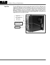
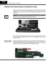
As you will notice in the photo below, we removed the backplane circuit board from
the D4–470 case to facilitate veiwing. Do not remove the backplane board to install
expansion boards.
Viewed as shown below, the PCI slots use the three white connectors indicated. The
ISA slots use the black connectors also identified below. The third PCI connector
from the top and upper ISA connector occupy the same slot position. This is the full
length slot. It can be use as either a PCI or ISA slot but not both.
Four ISA and PCI
Expansion Slots


