Chapter 4. FUNCTION BLOCK
4 - 7
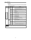
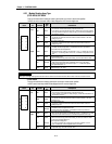
2) G6F-AD2A
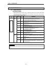
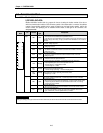
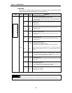
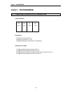
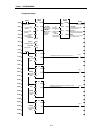
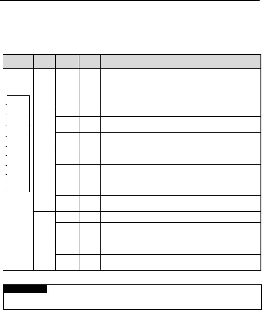
Module Initialization function block is a program for the use in setting the location number of the slot on
which the communication module of A/D conversion module of the master station is mounted, the address
number of communication module which a remote I/O station has, the base location number, and the slot
location number, and specifying the an available channel enable, a data type for A/D conversion, and
average process data.
Function
block
I/O Variable
Data
type
Descriptions
REQ BOOL
Function Block Execution Request Area on Rising Edge.
- The execution of write function block is requested in this area.
- If the status to be connected with this area is satisfied on the program operation and input
condition changes from low(0) to high(1), function block initialization for the module is
executed.
NET_
NO
USINT
The location number of the slot on which the transmission module of the master station is
mounted. -Setting range: 0 to 7
ST_NO USINT
Station number of the communication module which a remote I/O station has.
- Setting range : 0 to 63
BASE USINT
Base Location Number Area
- The base No. on which A/D conversion module is mounted is written on this area.
- Setting range : 0
SLOT USINT
Slot Location Number Area
- The slot No. on which A/D conversion module is mounted is written on this area.
- Setting range: 0 to 7
CH BOOL[4]
Available Channel Specification Area
- Available channels are specified in this area.
- Enabled channels are specified to 1 and disabled channels are specified to 0.
DATA
TYPE
BOOL[4]
Output Data Type Specification Area
- Output digital data type for each channel is specified in this area.
- 0 is for the r ange of –48 to 4047. - 1 is for the range of -2048 to 2047.
AVG_
EN
BOOL[4]
Average Process Enable Specification Area
- 1 is for the average processing. - 0 is for the sampling process.
Inpu
t
AVG_
NUM
USINT[4]
Set a constant of the average processing of the number of times.
- Setting range : 2 ~ 255
NDR BOOL
When function block execution is completed with no error, 1 is written. During the scan which
the execution condition has been made, 1 is continuing and at the next scan. 0 is written.
ERR BOOL
Error Data Display Area
- When error occurs during function block initialization, 1 is written and the operation comes
to stop. During the scan which the execution condition has been made, 1 is continuing
and at the next scan, 0 is written.
STAT USINT
Error Code Display Area
- When error occurs during function block initialization, the error code number is written.
Output
ACT BOOL[4]
Channel Operation Display Area
- The channel specified after executing the function block initialization with no error is
right, 1 is written and, on the non-specified channel, 0 is written.
REMARK
BOOL[4] and USINT[4] of data type means that the number of element is 4, and also this means the whole number of channels and channel number.
ST_N
O
BASE
SLOT
CH
DATA
TYPE
AVG_
EN
AVG_
NUM
ADR62INI
ACT
STAT
REQ
NET_
NO
ERR
NDR


