Chapter 8 MK Programming
8 - 5
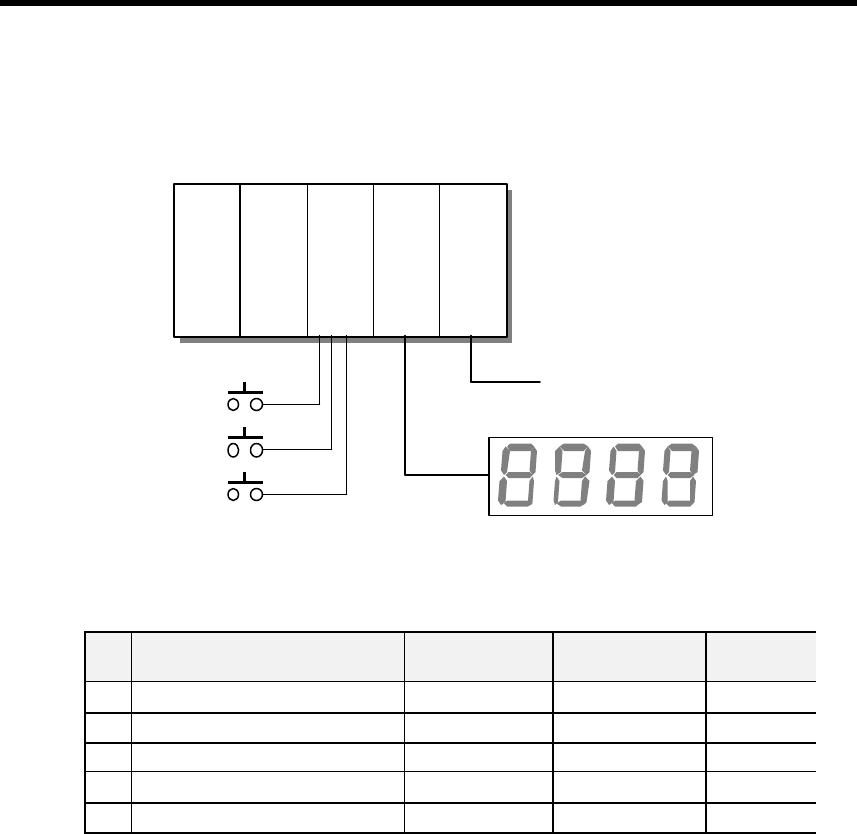
8.2.2 Output the analog input value by 7-segment display
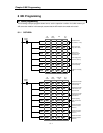
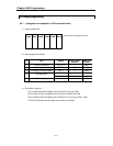
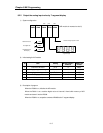
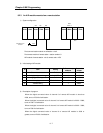
1) System configuration
(A/D module is mounted on slot 2)
2) Initial setting for A/D module
No Item Setting
Buffer memory
address
Data to be
written
1 Channel to be used Ch 0 0 h0001
2 Analog input type and range DC4~20mA 1 h0000
3 Averaging processing enable Ch 0 2 h0001
4 Averaging count Ch 0 : 10 times 3 h000A
5 Validate setting 7 h0001
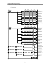
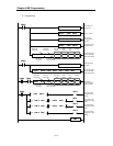
3) Description of program
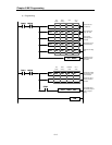
When the P0000 is on, initialize the A/D module.
When the P0001 is on, read the digital value of channel 0 from buffer memory of A/D
module and store it into the D0008.
When the P0002 is on, output the contents of D0008 to the 7 -segment display.
GM6-
PAFB
K3P-
07AS
G6I-
D22A
G6Q-
TR2A
G6F-
AD2A
P000 P001 P002
P0000
P0001
P0002
Initialize A/D module
Read digital value
Output digital value to
BCD display
Channel 0 : Analog input (DC4 ~ 20mA
7-segment display


