


12
206-4142
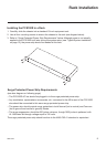
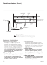
Typical System Installation
(see also Typical Setup Flow Chart and VPN Network Connections Overview on page 11)
1. Connect a 75 ohm BNC-to-BNC coaxial cable between ASI OUT on the PCS100R and ASI IN
on the modulator.
Note: The BNC cable must be less than 30 feet (9.2 meters) in length.
2. Connect an RF coaxial cable between IF OUT on the modulator and IF IN on the upconverter.
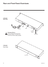
3. Connect one end of a CAT5 RJ-45 Ethernet cable to the NETWORK port on the PCS100R
rear panel, and connect the other end of the cable to the institution’s network.
4. Connect the PCS100R power supply to the POWER connector on the PCS100R rear panel.
5. Use the straight-through serial cable and, if necessary, the USB adapter to connect a PC to
the RS-232 port on the PCS100R rear panel. (This step will enable you to verify the network
connection once power is applied in step 7.)
6. Using HyperTerminal or an equivalent terminal emulation program on the PC, congure the
serial port as follows: Bits per second = 115200; Data bits = 8; Parity = None; Stop bits = 1;
Flow Control = None
7. Plug the PCS100R AC power cord into the surge protected power strip (see “Surge Protected
Power Strip Requirements” on page 9). When power is applied, the STATUS LED on the
PCS100R front panel will light, and you will see boot-up messages on the PC.
When the boot-up is complete, a System Information display identies important information
about the PCS100R, including the unit serial number, hardware ID (rmware version), software
versions, MAC address, and IP address, for example:
PCS100R Pro:Centric Server v3.3
SN: 001-12090025
Hardware ID: 0.0.0.15
OS version: Linux 2.6.33-zenith-pcs100r
OS release: #98 Mon Aug 9 09:36:05 CDT 2010
MAC Address: 00:0C:63:3B:00:0E
IP Address: 192.168.0.51
Datarate: high (38.8 Mbps)
Local time: Thu Jan 13 12:50:32 EDT 2011
8. Check the IP Address eld in the display. By default, the PCS100R uses DHCP; thus, the DHCP
server assigns an IP address to the PCS100R once the PCS100R successfully connects to the
network. If the IP Address eld shows an IP address, the PCS100R is up and running on the net-
work. If the IP Address eld is blank, refer to Troubleshooting information on the following page.
9. Connect the RF output on the upconverter to the RF distribution center combiner, and
balance the RF signal so that the signal level at the TV(s) is between 0 to +7 dBmV.
Caution: For proper system performance, the Pro:Centric signal level at the
TV input (ANTENNA IN) must be between 0 to +7 dBmV. Note that additional
equipment may be required to adjust the signal level.
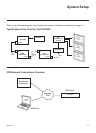
System Setup (Cont.)