User Manual Chapter 1 - General Description
N
N
e
e
t
t
w
w
o
o
r
r
k
k
P
P
o
o
w
w
e
e
r
r
S
S
w
w
i
i
t
t
c
c
h
h
Page
1-5
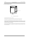
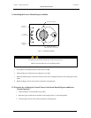
1.5 Manual Bypass Switch Operation
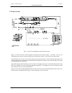
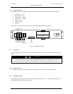
Fig 1.5 – Manual Bypass Switch Operation
Manual Bypass switch is used only when a fault occurs in the Network Power Switch and the control circuitry of the
Network Power Switch is to be checked. For doing this operation the load is connected to the bypass. For Normal
Operation, the position of the switch should be at Network Power Switch output position (i.e. horizontal)
If the load is to be fed through the source 1 Bypass, first it is to be unlocked and the knob should be rotated
upwards. To feed through source 2 bypass the knob is to be rotated downward.
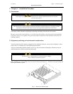
A mechanical interlocking arrangement is provided on this Bypass switch, by which the Hot swappable unit can be
removed only when load is connected to bypass. In normal operation when the load is connected to Network Power
Switch, the Hot swappable unit cannot be removed.
Operating Network Power Switch in Normal Mode (load connected to Network Power Switch output)
• Unlock the Manual Bypass Switch with the key provided.
• Depending upon the available healthy source (i.e. either Source-1 or Source-2 ) select it by changing the
Manual Bypass Switch position.
• Unlock the sliding module
• Pull out the Hot swappable sliding module out of the Network Power Switch, which contains (SCR
assembly, control circuitry).
Operating Network Power Switch in Bypass mode
• Insert the Hot swappable module into the Network Power Switch unit
• Lock the sliding module for preventing its accidental opening.
• Unlock the Manual Bypass Switch with the key provided
• Connect the Load output to Network Power Switch by changing the switch position to Network Power
Switch output.
• Depending on the priority switch, Load will get transferred to source-1, if the priority switch is on source1.
• The Static Switch output position LED will glow
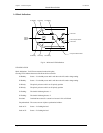
YELLOW LED
(LOAD ON S2)
YELLOW LED
(LOAD ON S1)
BYPASS ON S1 SOURCE
BYPASS ON S2 SOURCE
OUTPUT


