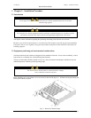
User Manual Chapter 3 – Installation Procedure
N
N
e
e
t
t
w
w
o
o
r
r
k
k
P
P
o
o
w
w
e
e
r
r
S
S
w
w
i
i
t
t
c
c
h
h
Page
4-1
4 Chapter 4 - Specifications
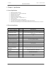
4.1 General Specifications
• Manual and Automatic Transfers
•
Sense and transfer time – less than 6 milliseconds
• Break-Before make switching
• Selectable preferred source
• Selectable auto/manual retransfer
• In-phase transfer window – adjustable from 5 ± 1°
• Convection cooling
• Hot swappable electronic static switching module
• Live mimic on Hot swappable unit for indicating load supply status & alarms
• Make before break manual bypass switch to transfer load from static switch to direct source 1 or source 2
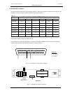
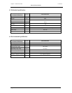
4.2 Electrical Specifications
ELECTRICAL
CHARACTERISTICS
UNITS
DESCRIPTION
Nominal Input Voltage
Volts
110, 115 or 120 volts singe phase, 3W+G, 50 Hz. Solidly grounded
power sources
Nominal Output current
Amps
25
Frequency
Hz
50 / 60
Source unhealthy status
-
Guaranteed Transfer to alternate source within –15 % of Vnominal
Load Power factor range
-
0.5 to unity leading or lagging
Load Crest factor
-
upto 3.5
In-Phase transfer window
-
Adjustable from 5 ± 1º
Source voltage distortion
% up to 10% THD
Overload capability
% 125% of continuous current for 2 hrs, 1000% for two cycles minimum.
Over current Protection
- By semi conductor fuse
Short circuit withstand
capability
Amps upto 20,000 symmetrical amps, protected by internal fusing.
Redundant Control Power
supplies
- taken from available source 1 and source 2
Integral Maintenance Bypass
- Make before break operation
Alarm contacts
- Eight Isolated Normally Open alarm & static switch Status contacts.
Unsynchronised transfer
6 milllisec for synchronized transfer and 16 millisec for unsynchronized
transfer.


