


User Manual Chapter 3 – Installation Procedure
N
N
e
e
t
t
w
w
o
o
r
r
k
k
P
P
o
o
w
w
e
e
r
r
S
S
w
w
i
i
t
t
c
c
h
h
Page
3-1
3 Chapter 3 – Installation Procedure
3.1 Introduction
WARNING
Do not apply electrical power to the Network Power Switch equipment before the arrival of the
commissioning engineer.
WARNING
The Network Power Switch equipment should be installed by a qualified engineer in accordance with the
information contained in this chapter and the drawing package shipped inside UPS cabinet.
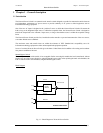
This chapter contains information regarding the positioning and cabling of the Network Power Switch.
Because every site has its peculiarities, it is not the aim of this chapter to provide step-by-step installation
instructions, but to act as a guide to the general procedures and practices that should be observed by the
installing engineer
.
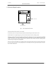
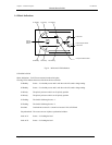
3.2 Equipment positioning and environmental considerations
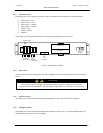
The Network Power Switch cabinets are designed to fit in standard 19-inch rack. In case of non-availability, it can be
kept on floor or as a tabletop item, with sufficient ground clearance.
The super switch module should be located in a cool, dry, clean environment with adequate ventilation to keep the
ambient temperature within the specified operating range.
WARNING
The Network Power Switch cabinet is connected with live voltages,
hence it should be located at safe place.
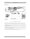
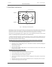
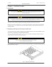
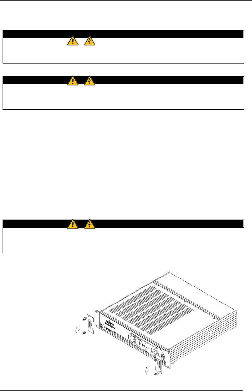
Before Installing, the ‘Transit Clamps’ are to be removed as shown in the figure 3.1. Without removing the clamps, the
Hotswap unit cannot be opened.
Fi
g
3.1
–
Removal of Transit Clam
p
s