


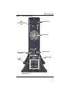
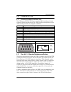

Controls and Indicators
15
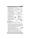
6.2 Standby/Manual Bypass Button
This button controls output power to connected load(s) and has
dual functions: Standby and Manual Bypass.
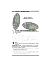
6.3 Load/Battery Level Indicators (4 Green, 1 Amber)
The load/battery level indicators have dual functions. During normal
mode operation LED indicators display the approximate electrical
load placed upon the UPS; and during battery mode operation LED
indicators display approximate battery capacity.
The UPStation GXT 2U is equipped with automatic and remote bat-
tery test features. The automatic test occurs every 14 days (this option
is user configurable) if mains has not been interrupted. Should the
battery fail this test, the red Fault indicator LED along with the A and
C diagnostic LEDs will illuminate and an alarm will sound (refer to
11.0 - Troubleshooting). The remote test feature functions with
MultiLink 3 software and can remotely initiate the battery test.
6.4 Fault Indicator LED (Red)
The Fault indicator LED is illuminated if the UPS has detected a
problem. Also, one or more of the load/battery level indicators may be
illuminated (refer to 11.0 - Troubleshooting).
6.5 Bypass Indicator LED (Amber)
The Bypass indicator LED is illuminated when the UPS is operating
from bypass power. An alarm will sound indicating the UPS detected
a problem, or the manual bypass function has been activated.
6.6 UPS ON Indicator LED (Green)
The UPS ON indicator LED is illuminated when the UPS inverter is
operating and supplying power to your connected loads.
!
CAUTION
While the UPS is in Normal Mode operation, pressing the
Standby/ Manual Bypass button once will put the UPS into
Bypass Mode.
Once the UPS is in Bypass Mode operation, press the Standby/
Manual Bypass button two distinct times (for about one
second each time) to turn off the UPS. Perform all necessary
shutdown procedures on connected loads before turning off the
UPS.