


46 Maintenance
Replacing a Helios Rectifier 200I/48 or 200E/48
1. Notify the alarm center of incoming alarms during this procedure.
2. Turn OFF the AC and DC circuit breakers on the rectifier to be replaced.
3. Remove the corresponding sense fuse on the front of the controller.
4. At the AC service panel, place the AC circuit breaker associated with this rectifier in the OFF
position.
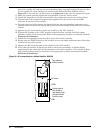
5. For a Helios Rectifier 200E/48 without an AC cord, remove the AC protective cover at the rear
of the rectifier and disconnect the AC cable inside the rectifier (refer to
Figure 32).
For a Helios Rectifier 200I/48 or 200E/48 equipped with an AC cord, unplug the AC cord from
the supply receptacle.
6. Remove the four bolts for the DC connections to the busbar risers at the rear of the cabinet.
7. Disconnect the control and signal cable from the DB25 connector at the rear of the rectifier.
8. Remove the mounting screws securing the rectifier to the cabinet.
9. Carefully slide the rectifier out of the cabinet.
CAUTION:
Due to the weight of the rectifier (55 kg - 120 lb) a manual lift or at least two
persons are required to remove the rectifier.
Reuse the shipping carton of the new rectifier to store or ship the removed unit.
10. Ensure that the AC and DC circuit breakers on the front panel of the new rectifier are in the
OFF position.
11. Lift the new rectifier to its position, rest it on the angle guides, and slide it into the cabinet.
CAUTION:
Due to the weight of the rectifier (55 kg - 120 lb) a manual lift or at least two
persons are required to install the rectifier.
12. Align the mounting holes of the rectifier with those of the cabinet uprights and secure the
rectifier in place using the eight mounting screws provided.
Note:
A star washer must be used on one of the mounting screws.
13. Reinstall the four bolts for the DC connections to the busbar risers at the rear of the cabinet
(removed in
Step 6).
14. Reconnect the control and signal cable into the DB25 connector at the rear of the rectifier
(disconnected in
Step 7).
15. Reconnect the AC cable disconnected in
Step 5
(or the AC cord that was unplugged).
16. At the AC service panel, place the AC circuit breaker associated with the rectifier in the ON
position.
17. Operate the AC circuit breaker of the new rectifier to the “ON” position.
18. With the DC breaker in the “OFF” position, adjust the float, equalize and high voltage
shutdown voltage levels as required. Refer to the appropriate rectifier user manual (see
6.0 -
Reference Documents).
19. Reinstall the sense fuse (RC) removed in
Step 3.
20. Ensure that the FLS/FS switch on the rectifier is set to the same position as that of the other
rectifiers in the power system.
21. Operate the DC circuit breaker of the rectifier to the “ON” position.
22. Verify that the rectifier is sharing the load by observing its ammeter. It should display
approximately the same value as the ammeters on the other rectifiers. If not, adjust its float
and equalize voltage levels as described in the appropriate rectifier user manual (see
6.0 -
Reference Documents).
23. Notify the alarm center of the end of the procedure.