


12
UPS On Indicator (Green)
The UPS On indicator is illuminated when the UPS inverter is operating and
supplying power to your connected loads.
Battery Indicator (Amber)
The Battery indicator is illuminated when the UPS is operating from the battery
system.
AC Input Indicator (Green)
The AC Input indicator is illuminated when utility power is available and within the
input specification.
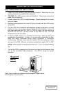
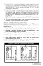
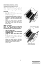
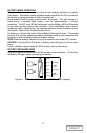
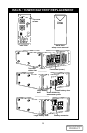
Output Voltage Selector Switches
The Output Voltage Selector Switches, located on the rear of the UPS, are
designed to allow selecting or changing the desired output voltage to match the
utility. The settings to choose from are 100, 110, 120, and 127 VAC output. The
factory default setting is 120 VAC.
NOTE: Never change the switch settings while UPS is on and powering
connected loads.
Switch positions for voltages:
100 VAC - both switches up
110 VAC - first switch up, second down
120 VAC - both switches down (Factory Default)
127 VAC - first switch down, second up
NOTE: Setting output voltage to 100 VAC will cause UPS unit to be derated to
90% of the VA and Watt rating listed in specification section.
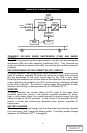
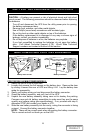
OPERATION
NORMAL MODE OPERATION
During normal operation, utility power provides energy to the UPS. The filters,
the power factor conditioning circuit and the inverter process this power to
provide computer grade power to connected loads. The UPS maintains the
batteries in a fully charged state.
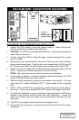
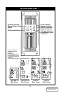
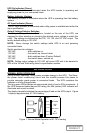
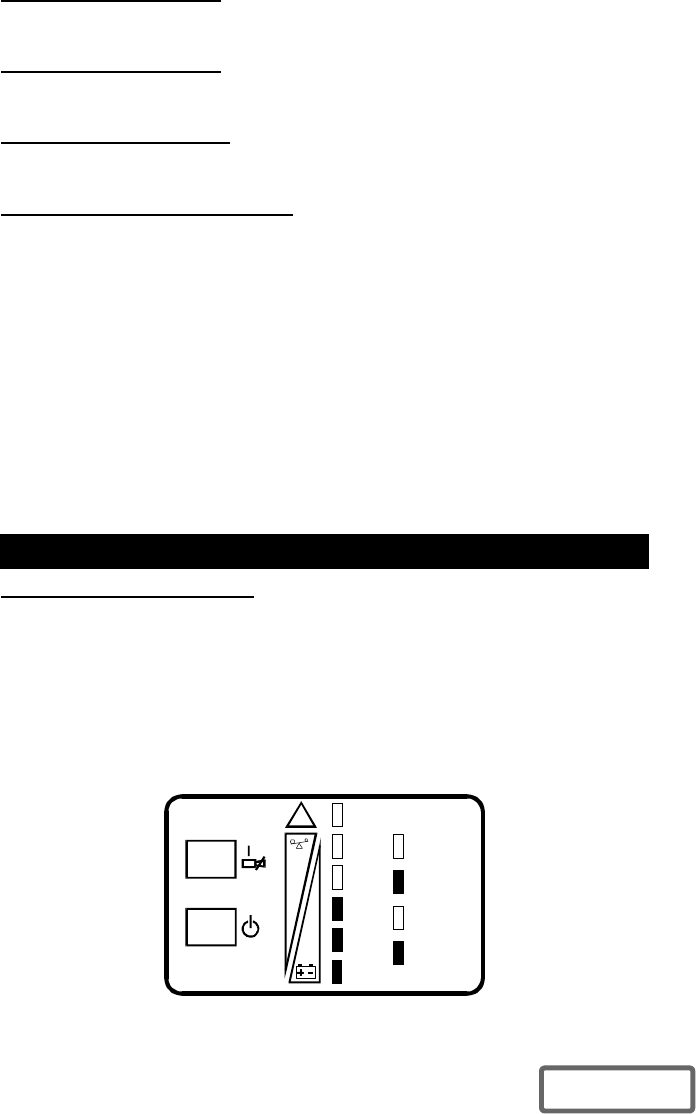
The four green LEDs indicate an approximate level of load in 25% increments. If
the UPS becomes loaded beyond full rating, the fifth (amber) LED indicator will
illuminate and sound an alarm.
The display template indicates the percentage of load on the UPS output. Figure
1 displays approximately 51-75% loading.
!
Fault
BYPASS
UPS
ON
BATTERY
AC
INPUT
100%
76-100%
51-75%
26-50%
0-25%
Figure 1- Normal Mode Operation at 51-75% loading
DISCONTINUED
PRODUCT