


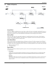
Installation
12
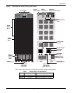
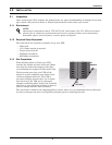
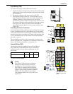
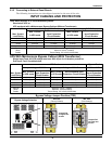
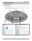
Input Wiring (TB1)
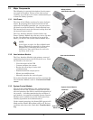
To connect the input wiring, follow these steps:
1. Locate the input wiring access, remove the knockout and
pull the three input wires through it, allowing some slack
for installation.
2. Secure the conduit to the rear panel of the UPS.
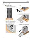
3. Input Power cables connect to screw terminals on the
Input Terminal Block located to the right of the Bypass
Voltage Terminal. Connect the wires to the block
connections as shown below. Using a torque wrench, turn
the screws clockwise until tightened to the proper torque
value (28 in-lb). Insert the ground wire through the
grounding lug and tighten it to the proper torque value
(120 in-lb).
Grounding Conductor Installation
An insulated grounding conductor must be identical or larger
in size, insulation material, and thickness as the grounded
and ungrounded branch circuit supply conductors. This cable
must be green with or without one or more yellow stripes and
is to be installed as part of the branch circuit that supplies
the unit or system.
The grounding conductor is to be grounded to earth at the
service equipment or, if supplied by a separately derived sys-
tem, at the supply transformer or generator set.
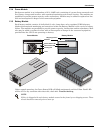
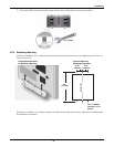
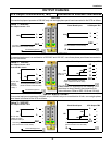
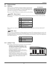
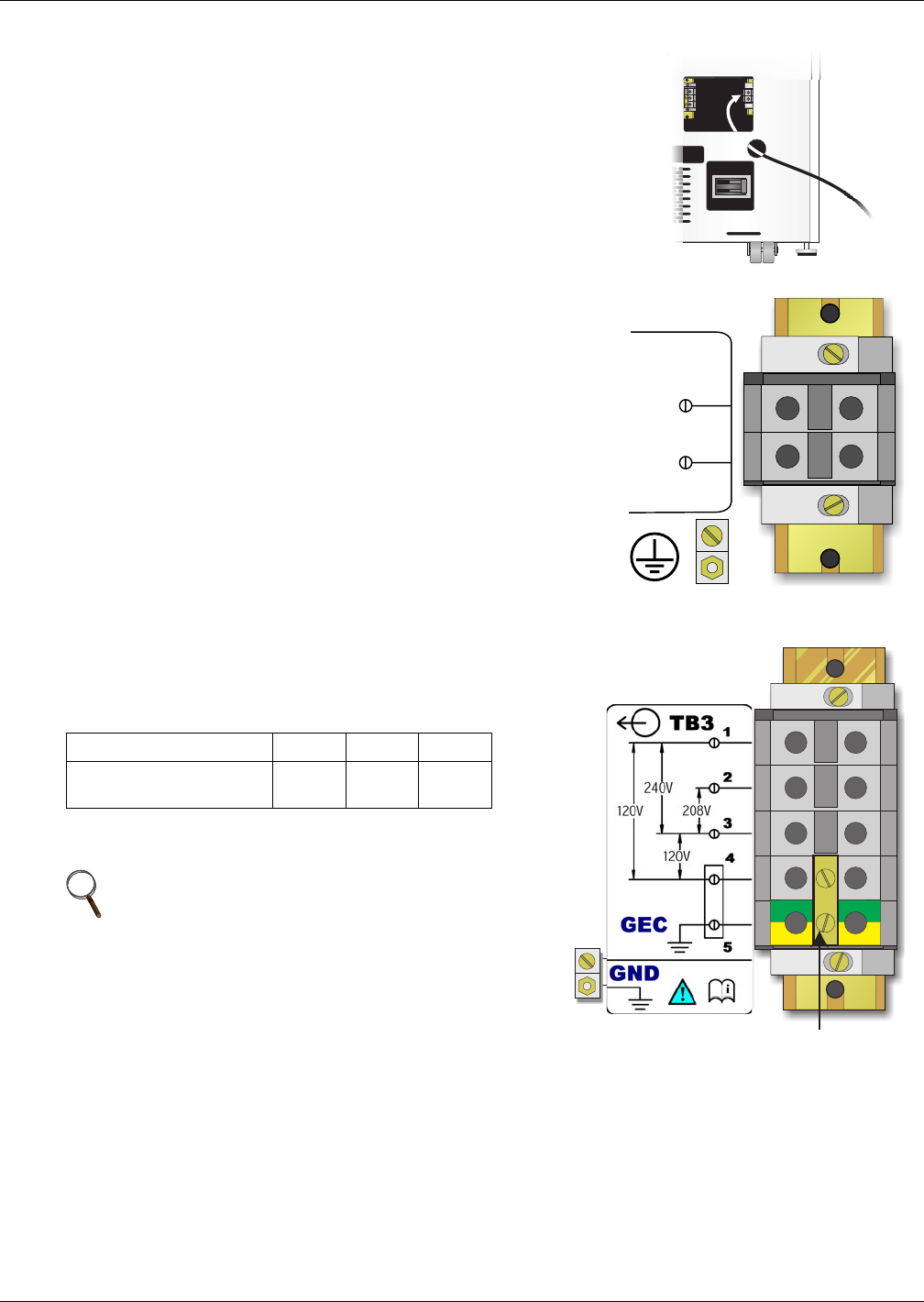
Output Wiring (TB3)
Output wiring may be configured one of two different
ways (240/120 or 208/120). Refer to the chart below
and the diagram at right when configuring the out-
put wiring.
Voltage 120 208 240
Between terminals 1 & 4
3 & 4
2 & 3 1 & 3
Use only the connections listed above. Other connections will
produce nonstandard voltages.
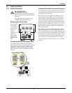
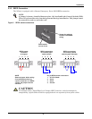
NOTE
The Nfinity UPS contains an isolation
transformer that generates a neutral
conductor for the connected equipment.
The UPS is a separately derived source
and contains a neutral to ground bonding
jumper. A grounding electrode conductor
(GEC) must be installed in accordance
with national and local wiring codes and
regulations.
TB1
L1
L2
2
1
Note the Neutral / Earth
jumper on the terminal
above