


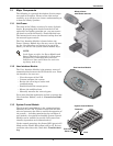
Installation
14
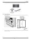
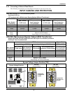
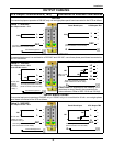
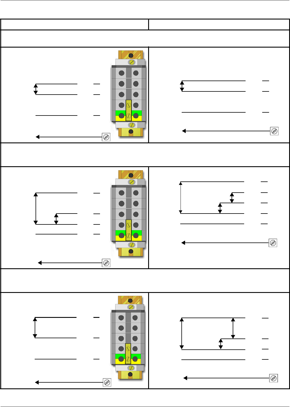
OUTPUT CABLING
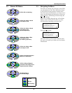
UPS Output Terminal Block (TB3) Connection to External Panel Boards
208 VAC
If connected equipment operates at 208VAC only, use a single-phase panel board connected to the UPS as follows.
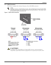
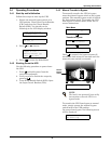
208 VAC and 120 VAC
If connected equipment is a combination of 208 VAC and 120 VAC, use a three-phase panel board connected to
the UPS as follows.
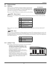
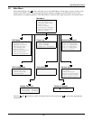
240VAC and/or 120VAC
If connected equipment operates at 240VAC only or 120VAC only or is a combination of both, use a single-phase
panel board connected to the UPS as follows.
1
2
3
4
5
Setup 1 - 208 VAC
208
Grounding Electrode Conductor
(Field connection must be made)
L
L
GEC
Max output current = 77A
Connected Equipment
Ground
208
UPS Output TB3
Panel Board Input
Grounding Electrode Conductor
(Field connection must be made)
1
2
3
4
5
L
L
GEC
G
1
2
3
4
5
Setup 2 - 120 VAC
120
N
208 VAC also
available
as shown
connected
in Setup 1
Grounding Electrode Conductor
(Field connection must be made)
Max output current = 67A
each 120 VAC circuit
Connected Equipment
Ground
L
L
GEC
120
Note: L2 to N
is 88 VAC
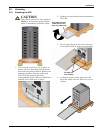
CAUTION: It is important for the installing
electrician to clearly identify the connections for
future reference. Refer to NEC 215-8 and 210-4
(
d
)
.
208
120
UPS Output TB3Panel Board Input
120
1
2
3
4
5
L2
N
L1
L3
G
Grounding Electrode Conductor
(Field connection must be made)
GEC
1
2
3
4
5
Setup 3 - 240 VAC
240
120 VAC also
available as shown
connected in Setup 2
Grounding Electrode Conductor
(Field connection must be made)
Max output current = 67A
Connected Equipment
Ground
L
L
GEC
240
120
120
UPS Output TB3Panel Board Input
1
2
3
4
5
N
L
L
G
Grounding Electrode Conductor
(Field connection must be made)
GEC