


The blue wire must be connected to the terminal which is marked with the letter
“N” or colored black.
The brown wire must be connected to the terminal which is marked with the letter
“L” or colored red.
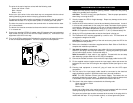
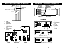
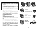
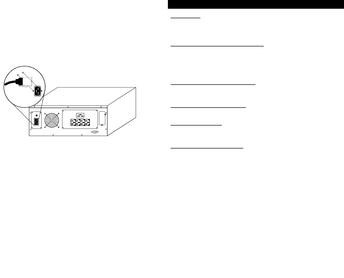
13. Connect the supplied IEC 320-10 output cable (B) between the load equipment
input socket (D) and one of the UPS AC output sockets (E). Connect all load
equipment to the UPS in this way.
14. Turn on the UPS, by pressing the On/Off button, then turn on the connected load
equipment. The UPS is ready for normal operation.
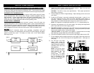
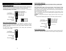
CONTROLS AND INDICATORS
On/Off Button
The On/Off button controls output power to connected load(s).
CAUTION: Pressing the On/Off button when AC mains is not present will cause the
UPS to begin operating from battery. This should not be performed unless the UPS
input is connected to a properly earthed socket.
Load/Battery Level Indicators (ALL GREEN)
The Load/Battery Level Indicators have dual functions. During normal mode
operation, LED indicators display electrical load placed upon the UPS; and during
battery mode operation, LED indicators display battery capacity remaining. Each
LED designates a 25% load or battery capacity increment. All four LED indicators
illuminate at full load/battery capacity. If the UPS becomes loaded beyond full rating,
the top LED indicator will flash continuously while an alarm sounds.
Mains/Battery Status Indicator (GREEN)
An illuminated LED indicates the power button is on and mains power is available. A
flashing LED along with an alarm signifies mains voltage is out of specification and
UPS is operating in battery mode.
Mains High/Low Indicator (AMBER)
An illuminated LED indicates the UPS is correcting mains power, due to a mains
overvoltage or undervoltage condition.
Fault Indicator (GREEN)
The Fault indicator is the second uppermost LED (contained in load/battery level
indicators). A flashing LED indicates the UPS has detected a problem. An alarm
sounds to alert that the UPS requires attention. Refer to Troubleshooting Guide.
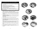
Alarm Silence/Battery Test Button
The Alarm Silence/Battery Test button serves a dual purpose. During normal mode
operation, press button for at least one half second to test capacity of the battery
system. The UPS will operate in battery mode for approximately 15 seconds. The
illuminated LED indicators in Load/Battery Level determine battery mode capacity in
25% increments.
During battery mode operation or active alarm condition, this button functions as the
alarm silence feature. Pressing this button for at least one half second will silence the
alarm. After the alarm is silenced, the PowerSure™ Interactive will reactivate the
alarm system to alert of additional problems. The low battery alarm is the single
alarm that cannot be silenced.
During a Battery Test, if the top two LEDs do not illuminate allow the UPS to
recharge the batteries for 24 hours. After 24 hours, retest the batteries. If the
batteries have been retested and the top two LEDs still do not illuminate, contact your
dealer or Liebert Technical Support (LTS) for a battery replacement kit.
9 10