


Installation, Operation and Maintenance Manual 14 Liebert TVSS Units SL-22085 Rev 2, 11/2006
Surge Suppression Systems
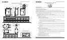
Connection
The AccuGuide assembly is provided in standard lengths of 5, 8, 10, 12, 15, and 20 feet. Each end of the assembly will include an
additional fi ve feet of #10, 8, 6, or 4 AWG pigtails for connection to the service and to the surge protective device (SPD). Gauge of
the pigtail is based on the SPD lug size. See chart below for units and acceptable wire ranges. An additional 10 gauge-grounding
conductor is provided with the AccuGuide assembly for use as an equipment ground.
Interceptor II Units Acceptable Wire Range
All Units - No Disconnect #14 – 2/O
SI016-025 – With Disconnect #8 – 1/O
SI032-100 – With Disconnect #14 – 2/O
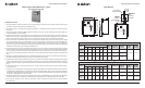
Conduit
The AccuGuide assembly is sold without conduit. If conduit housing is required, the following conduit and fi tting sizes apply:
Equipment Performance
The ideal SPD installation locates the suppression as close to the protected bus as possible. This product was designed to address
those instances when a close installation is not possible. However, while the voltage drop experienced with an AccuGuide
assembly is signifi cantly reduced, care should be taken to keep connection lengths to a minimum.
Each end of the AccuGuide assembly is shipped with fi ve-foot pigtails. The length is offered as a worst-case need for the panel or
switchgear end (our SPD will be much less than 5 feet). We recommend cutting the pigtail to the shortest length possible.
No. of Conductors Conduit Size (in.)
1 Coax Cable, 1 GND 1
2 Coax Cable, 1 GND 1-1/4
3 Coax Cable, 1 GND 1-1/4
4 Coax Cable, 1 GND 1 1/4
5 Coax Cable, 1 GND 1 1/2
6 Coax Cable, 1 GND 1 1/2
7 Coax Cable, 1 GND 1 1/2
Caution: Pigtails must be supported if pulling AccuGuide assembly through conduit. Grip only the blue coaxial cable
body when pulling the assembly through conduit. Do not pull AccuGuide assembly using the pigtails or damage
may occur.
LM Units Acceptable Wire Range
All Units - No Disconnect #14 – #2
LM060-080 – With Disconnect #8 – 1/O
LM100-250 – With Disconnect #14 – 2/O
Surge Suppression Systems
Installation, Operation and Maintenance Manual 15 Liebert TVSS Units SL-22085 Rev 2, 11/2006
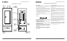
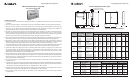
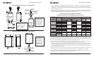
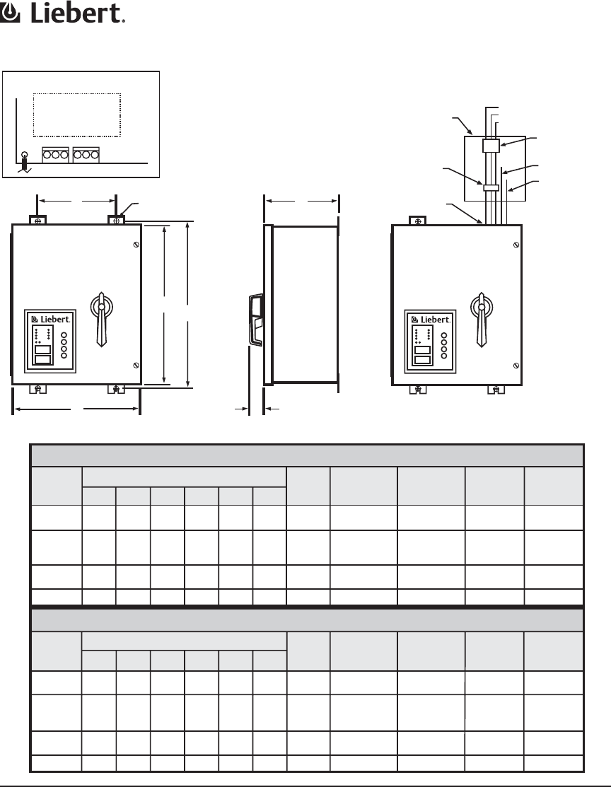
Dimensional Information
Interceptor II Series - Type SI
E
F
(4X)
B
A
D
C
1.840
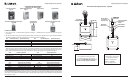
Max.
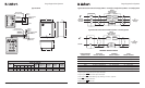
Service Panel for
Loads to be Protected
Phase L1/A
Phase L2/B
Phase L3/C
Disconnect/Main
Breaker for
Panel
Neutral Buss
Ground Buss
Dedicated
Disconnect
(Optional)
Recommended Wire
Entrance
Summary Alarm Contacts (X2)
Pin 1 = Normally Open
Pin 2 = Common
Pin 3 = Normally Closed
TB1 TB2
1 2 3 1 2 3
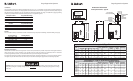
Interceptor II, Type SI
Interceptor II, Type SI, with Rotary Disconnect
Unit
Dimensions (Inches)
Weight
(lbs)
Suggested
Breaker Size
Suggested
Wire Size
(AWG)
Allowable
Breaker
Range
Allowable
Wire Range
Dimensions (Inches)
Unit
Weight
(lbs)
Suggested
Breaker Size
Suggested
Wire Size
(AWG)
Allowable
Breaker
Range
Allowable
Wire Range
A B C D E F
A B C D E F
SI016
SI025
SI032
SI040
SI050
SI060
SI075
SI100
16
20
20
20
12
16
16
20
8
8
8
8
17.25
17.25
21.25
21.25
9.5
10
10
14
0.44
0.44
0.44
0.44
35
49
55
85
60 A
80 A
80 A
100 A
#6
#4
#4
#2
15A – 175A
15A – 175A
15A – 175A
15A – 175A
#14 – 2/O
#14 – 2/O
#14 – 2/O
#14 – 2/O
SI016
SI025
SI032
SI040
SI050
SI060
SI075
SI100
16
16
20
24
16
16
20
20
8
8
8
8
17.25
21.25
21.25
21.25
10
10
14
18
0.44
0.44
0.44
0.44
45
58
85
95
60 A
80 A
80 A
100 A
#6
#4
#4
#2
15A – 150A
15A – 175A
15A – 175A
15A – 175A
#14 – 1/O
#14 – 2/O
#14 – 2/O
#14 – 2/O
Liebert Interceptor II Printer S16 16 12/29/06 1:38:01 PM