


Installation, Operation and Maintenance Manual 12 Liebert TVSS Units SL-22085 Rev 2, 11/2006
Surge Suppression Systems
Liebert PanelGuard Series - Type LPGE
Surge Protective Device (SPD)
Installation Instructions
1. Insure that all power is removed before beginning installation. A qualifi ed licensed electrician shall install all electrical
connections
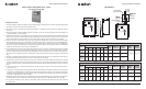
2. The unit is provided in a NEMA 1 rated industrial-use enclosure and should be installed in areas only appropriate for NEMA 1.
3. The unit is to be wall mounted in an area where suffi cient access and working space around the cabinet can be assured. (See
NEC Section 110-16.) Position the SPD opposite the incoming feed to the panelboard. For example, if the panelboard is
supplied through the top of its enclosure, mount the SPD at the bottom of the panelboard.
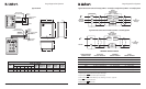
4. Knockouts for connection of the suppressor to the panelboard back box are provided on top, bottom, and sides of the unit’s
enclosure. The diameters of the knockouts vary to accommodate conduit / collar diameters of 1/2 in. to 1 1/4 in. The proper
size busing (diameter and length) must be selected to protect the conductors as they transition from the SPD to the panelboard
conductor, and to maintain the cosmetic integrity of the Liebert LPGE Series Surge Protection Device.
5. When connecting the SPD to the panelboard, it is important that the panelboards interior and the SPD are protected from any
metal shavings, which may result. An inspection and cleaning of the LPGE should be performed before applying power.
6. Representative samples of this product have been investigated by Underwriters Laboratories, Incorporated to withstand,
without exposing live circuits or components at system voltages and fault currents of up to 200,000 AIC, as described in the
Standard for Safety, Transient Voltage Surge Suppressor (TVSS), Standard 1449, Second Edition, dated August 15, 1996.
7. An external circuit breaker is not necessary for over-current protection. However, it is recommended that the SPD be connected
in series with a 30A circuit breaker. The SPD shall be connected in accordance with all national and local electrical codes.
8. To obtain the suppression voltage ratings (SVRs), as obtained by Underwriters Laboratory, Incorporated, in accordance with
the Standard for Safety, Transient Voltage Surge Suppressors (TVSS), Standard 1449, Second Edition, dated August 15, 1996,
marked on this product, #8 AWG wire must be utilized to connect the unit to your facilities power grid. Connections made
with conductors other that #8 AWG may result in different SVRs.
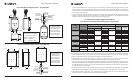
9. Connect black wires (line or phase) marked L1/A, L2/B or L3/C, the white wire (neutral) marked N, and the green wire (ground)
marked G, of the SPD using the wire range listed in the table below in accordance with the National Electric Code (NEC) Article
285 and all local codes. To yield the best performance of the SPD within the electrical distribution system, keep all conductors
as short as possible and avoid sharp bends.
10. Connection to the Form ‘C’ contacts shall be with #18 – 22 AWG. Contacts are rated 5 amps at 250 VAC maximum with a
power factor of 1.0.
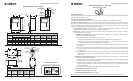
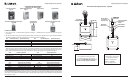
11. Apply power. The surge protector is fully operational when the GREEN LEDs are illuminated. If the GREEN LEDs are extinguished,
check to ensure that power is applied to the SPD. If an abnormal indication is present, remove power to the SPD and contact
Liebert/Emerson Network Power Surge Protection at 1-800-288-6169 or 1-607-724-2484.
12. Periodically monitor the status of the LEDs. Reduced protection exists if the GREEN LEDs are extinguished. Please contact
Liebert/Emerson Network Power Surge Protection at 1-800-288-6169 or 1-607-724-2484.
13. The protection modules in these SPDs are replaceable, contact Liebert/Emerson Network Power Surge Protection
for replacement.
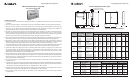
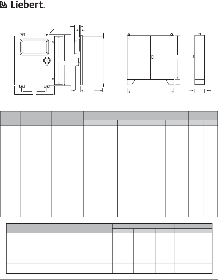
Dimensions (Inches) Weight
A B C Lbs Kg
FxxxD800 Three Phase Delta 60.0 48.0 12.0 500 227
FxxxY800 Three Phase Wye 60.0 48.0 12.0 530 241
FxxxD1200 Three Phase Delta 60.0 48.0 20.0 700 318
FxxxY1200 Three Phase Wye 60.0 48.0 20.0 750 340
FxxxD2000 Three Phase Delta 60.0 48.0 20.0 875 397
FxxxY2000 Three Phase Wye 60.0 48.0 20.0 950 431
FxxxD4000 Three Phase Delta 60.0 48.0 20.0 1175 533
FxxxY4000 Three Phase Wye 60.0 48.0 20.0 1300 590
NOTE: Consult factory for special instructions on caseless and switchgear models.
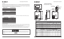
Current Model Dimensions (Inches) Weight
Rating XXX = VOLTAGE Application
A B C D E F Lbs Kg
FxxxN/L30 Single Phase 24.0 20.0 9.0 21.25 10.0 .44 35 15.9
FxxxS30 Split Phase 24.0 20.0 9.0 25.25 14.0 .44 45 20.4
FxxxD30 Three Phase Delta 24.0 20.0 9.0 25.25 14.0 .44 50 22.7
FxxxY30 Three Phase Wye 24.0 20.0 9.0 25.25 14.0 .44 60 27.2
FxxxN/L60 Single Phase 24.0 20.0 9.0 21.25 10.0 .44 35 15.9
FxxxS60 Split Phase 24.0 20.0 9.0 25.25 14.0 .44 45 20.4
FxxxD60 Three Phase Delta 24.0 20.0 9.0 25.25 14.0 .44 50 22.7
FxxxY60 Three Phase Wye 24.0 20.0 9.0 25.25 14.0 .44 60 27.2
FxxxN/L100 Single Phase 30.0 24.0 9.0 25.25 14.0 .44 60 27.2
FxxxS100 Split Phase 30.0 24.0 9.0 31.25 18.0 .44 70 31.8
FxxxD100 Three Phase Delta 30.0 24.0 9.0 31.25 18.0 .44 70 31.8
FxxxY100 Three Phase Wye 30.0 24.0 9.0 31.25 18.0 .44 80 36.3
FxxxN/L225 Single Phase L – N 30.0 24.0 9.0 25.25 14.0 .44 60 27.2
FxxxS225 Split Phase 30.0 24.0 9.0 31.25 18.0 .44 70 31.8
FxxxD225 Three Phase Delta 30.0 24.0 9.0 31.25 18.0 .44 70 31.8
FxxxY225 Three Phase Wye 30.0 24.0 9.0 31.25 18.0 .44 80 36.3
FxxxD400 Three Phase Delta 48.0 36.0 12.0 49.25 30.0 .44 275 125
FxxxY400 Three Phase Wye 48.0 36.0 12.0 49.25 30.0 .44 300 136
Surge Suppression Systems
Installation, Operation and Maintenance Manual 17 Liebert TVSS Units SL-22085 Rev 2, 11/2006
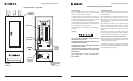
Active Tracking Filter Series - Type F
Typical Cabinet Data (30 to 400Amps) Typical Cabinet Data (800 to 4000Amps)
F
B
A
D
E
B
2.0” Max.
Large Bezel 2.0” Max. (Options)
Small Bezel .50” Max. (No Options)
A
C
12”
Application
30A
60A
100A
225A
400A
800A
1200A
2000A
4000A
Current
Rating
Model
XXX = VOLTAGE
Liebert Interceptor II Printer S14 14 12/29/06 1:38:00 PM