


System Grounding and Bonding
The performance and safety of any SPD system is dependent
on proper grounding and bonding. Grounding is required for
safety. Correct implementation also enhances equipment
performance. Incorrect grounding can reduce or impede the
SPD’s operation.
All electrical circuits to the SPD must include an equipment-
grounding conductor as required by the NEC and local codes.
An insulated grounding conductor is required in addition to any
metallic raceway, which may be used as a grounding conductor.
For parallel-connected SPDs, the grounding conductor should
be the same wire size as the associated power conductors.
Grounding conductors must be routed with the associated
power conductors in the same raceway (conduit).
When metallic raceways are used, adequate electrical
continuity must be maintained at all raceway connections,
particularly raceway terminations to the electrical enclosures.
The use of isolating bushings or other means to interrupt a
metallic conduit run is a potential safety hazard and is not
recommended.
Grounding Electrode — Surge protective devices do not
discharge all surges to ground (earth). Surge protective
devices divert the surge current back to its source to complete
the electrical circuit.
In the case of lightning whose potential is developed with
respect to the earth, the SPD diverts the surge current to
the grounding electrode (earth connection). However, for
most transient surges that are developed by switching loads,
the SPD diverts the surge current back to its source without
involving the grounding electrode.
For proper SPD performance, the service entrance grounding
electrode system must comply with the NEC by having all
available electrodes (building steel, metal water pipe, driven
rods, concrete encased electrodes, etc.) properly bonded
together and connected to the power system grounding.
The use of a separate grounding electrode to ground the SPD
defeats the effectiveness of the SPD, is a potential safety hazard,
may cause equipment damage, is an NEC violation (reference
NEC 250-51 and 250-54), and is not recommended.
FOR PROPER AND SAFE OPERATION, THE NEUTRAL, (IF
PROVIDED), MUST BE RELIABLY CONNECTED TO THE
NEUTRAL OF THE SOURCE. FAILURE TO PROVIDE A RELIABLE
NEUTRAL CONNECTION MAY RESULT IN MODULE FAILURE!
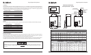
SPD Monitoring
External Status Indicators — These indicators provide a
summary of the status of the surge SPD module. For normal
conditions, the green “OK” LED is illuminated and the red
“Service” LED is extinguished. If the surge SPD module
requires replacement, the green “OK” LED is turned off and
the red “Service” LED illuminated.
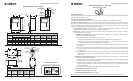
Summary Alarm Contact (if applicable) — Summary alarm
Form C (1 N.O. and 1 N.C.) relay contacts may be provided for
remote indication of the failed surge SPD module.
Contacts are rated 5 amps at 250 VAC maximum with a power
factor of 1.0. For units with Summary Alarm Contacts, access
to the contacts are typically provided via contact terminals
located on the printed circuit board mounted on the inside of
the unit’s cover.
Transient Counter (if applicable) – Transient counters are
provided for transient voltage surge monitoring. The counter
totalizes surges monitored since the last counter reset.
The transient counter monitors line transient voltages. The
circuit counts all surges that deviate from the line sine wave.
The factory setting is 30% over nominal line voltage. Other
settings include 50%, 70%, and 100%.
Swell Counter (if applicable) — The swell counter monitors
line to line & line to neutral voltages. It is factory set to record
whenever the peak voltage on any normal mode exceeds the
nominal voltage of the TVSS for more than 10ms. This counter
records temporary line over voltages that may result from
utility switching, line regulation problems, etc.
Audible Alarm (if applicable) — If the surge SPD module
requires replacement, an audible alarm is activated to draw
attention to the fact that repair service is required to restore
the system to normal operation. An audible alarm disable is
provided to silence the alarm. The system will automatically
reset itself after repair. The audible alarm switch and “Service”
LED can be tested by activating the “Test” switch on the
system monitor panel. For information on the AccuVar Series
Alarm, see page 16.
Installation, Operation and Maintenance Manual 6 Liebert TVSS Units SL-22085 Rev 2, 11/2006
Surge Suppression Systems
Surge Suppression Systems
Installation, Operation and Maintenance Manual 23 Liebert TVSS Units SL-22085 Rev 2, 11/2006
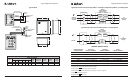
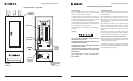
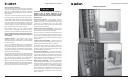
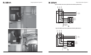
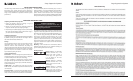
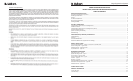
Example Installations
Liebert Interceptor II Printer S8 8 12/29/06 1:37:57 PM