2.3.3 Status LEDs
This Switch comes with a complete range of LEDs. The table below lists each LED’s name, color and a brief description of its
function.
One (1) for power On/Off.
One (1) per port for Link/Activity.
One (1) per port for Full-Duplex/Collision.
Four (4) for TRUNK Groups status.
Two (2) for Home VLAN status.
Name Color Function
Pwr Green Lit: Power "On"
LINK/ACT Green Lit: When the port has a valid physical connection (Link) with another
device.
Blinks: When the port is sending or receiving data (Activity).
FD/COL Amber Lit: When the port is set to Full-Duplex mode.
Blinks: When a collision is detected, in Half-Duplex mode.
A Green Lit: TRUNK AGroup Enable (Port#1, #2, #9, #10 are a TRUNK Port)
Blink: When the TRUNK Group has a port link Failure with another device.
B Green Lit: TRUNK B Group Enable (Port#3, #4, #11, #12 are a TRUNK Port)
Blinks: When the TRUNK Group has a port link Failure with another device.
C Green Lit: TRUNK C Group Enable (Port #5, #6, #13, #14 are a TRUNK Port)
Blinks: When the TRUNK Group has a port link Failure with another device.
TRUNK
D Green Lit: TRUNK D Group Enable (Port #7, #8, #15, #16 are a TRUNK Port)
Blinks: When the TRUNK Group has a port link Failure with another device.
A Amber Lit: Support 14 VLANs (Port#1 #7, #9-#15) with 2 overlapping ports
(Port#8, #16) topology
Home
VLAN
B Amber Lit: Support 15 VLANs (Port#1
#15) with 1 overlapping port (Port#16)
topology
We provide Four (4) LEDs to indicate the TRUNK status.
The TRUNK LED will be lit on when the trunk is enable, it will blink when any physical port link failures occur within the enabled
trunk port.
If the TRUNK LED blinks during the normal operation, please check the trunk group ports link status.
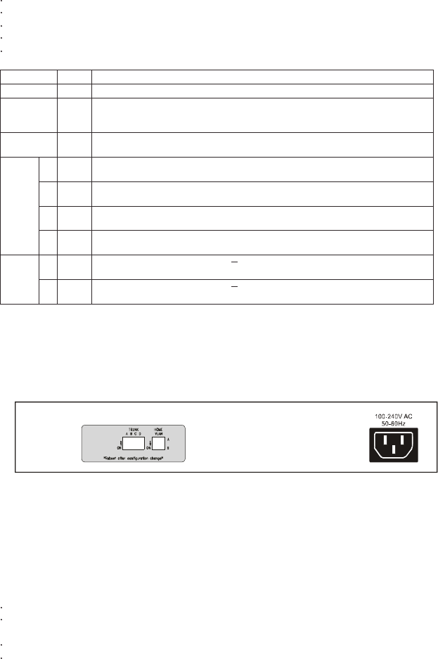
2.4 The Rear Panel
16-Port Switch
2.4.1 Power Socket
The Power Socket is designed to be used with the power cord included in the product package.
Attach the female end of the cord to the power connector on the back panel.
Attach the male end of the cord to a grounded power outlet.
Note: To reset the switch, Remove the power cord and re-attach it .
The switch must be reset when the MAC Address table needs to be rebuilt.
The switch must be reset when the configurations (on real panel) are changed.


