6
2.4.2 DIP-Switch
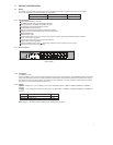
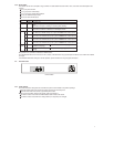
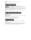
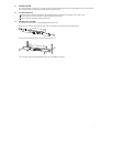
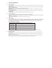
This Switch provides DIP-Switches setting to configuration, the configuration setting as below:
a. Home VLAN
We have provided two DIP-Switches for the Home VLAN setting.
Left side DIP-Switch Right side DIP-Switch
SW up Home VLAN Disable Home VLAN TYPE A
SW down Home VLAN Enable Home VLAN TYPE B
Home VLAN TYPE A: Select 14 VLANs (port#1 #7, #9 #15) with two overlapping ports (port#8, #16) topology. (VLAN1:
port#1, #8, #16; VLAN2: port#2, #8, #16; VLAN3: port#3, #8, #16, …; VLAN14: port#15, #8, #16)
Home VLAN TYPE B:
Select 15 VLANs(port#1 #15) with one overlapping port (port#16) topology. (VLAN1: port#1, #16; VLAN2:
port#2, #16; …; VLAN15: port#15, #16)
This function for network topology security configuration. When the Port-Based security function is enabled, the 16-Ports Switch
can be configured as 14 (or 15) individual VLANs that share the same two (or one) overlapping port(s). This 14 VLANs or 15
VLANs topology is useful to allow home networks to share common servers or routers, this function can be used on Fiber To The
Home (FTTH) or Ethernet To The Home (ETTH) application.
Note: Only when the left side DIP-Switch move to “ON”, the function of the right side DIP-Switch would be active.
b. TRUNK
We have support Four DIP-Switches for the TRUNK Port setting.
ABCD
SW up TRUNK ADisable TRUNK B Disable TRUNK C Disable TRUNK D Disable
SW down TRUNKAEnable TRUNK B Enable TRUNK C Enable TRUNK D Enable
TRUNKA: Port#1, #2, #9, #10
TRUNK B: Port#3, #4, #11, #12
TRUNK C: Port#5, #6, #13, #14
TRUNK D: Port#7, #8, #15, #16
If the trunk function enable, it can be provided 800Mbps bandwidth between two devices, it is useful to allow high bandwidth in
Backbone or server connection.
Note: If the Home VLAN function is enabled, it will disable the TRUNK function setting.
c. 100FX (100BASE-FX operation mode setting) (only for Switch w/ Fiber port)
This DIP-Switch is setting to configuration 100Mbps Half-/Full-Duplex on the Fiber port.
Operation mode
SW up 100Mbps Half-Duplex
SW down 100Mbps Full-Duplex
Note: When the DIP-Switches configuration changes, the Switch had to be “Power Reset”. Please reboot after
configuration change.
2.5 Broadcast Storm Control
The Broadcast Storm Control discards broadcast frames when the number of cumulated non-unicast frames is over the
threshold, in order to prevent Network Traffic congestion bringing the Network to a halt. In this Switch, each port will drop
broadcast packets (Destination MAC ID is ff ff ff ff ff ff) after receiving continuous 64 broadcast packets. The counter will be reset
to 0 every 800ms or when receiving any non-broadcast packets. (Destination MAC ID is not ff ff ff ff ff ff)


