


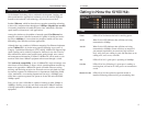
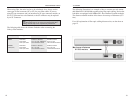
10/100 Hubs
Two different Fiber Optic modules are available for the rack-mountable
10/100 Hub (EF2H16 and EF2H24):
EF2HSC: 100BaseFX 1-Port Transceiver Module (SC)
EF2HST: 100BaseFX 1-Port Transceiver Module (ST)
Each Fiber port has two connectors, a transmit (TX) and a receive (RX). To
connect two modules together, you must run a Multi-mode fiber cable from
the transmit connector on one module to the receive connector on the other. If
you are looking at the back of the hub, the connector on the right is the
receiver and the connector on the left is the transmitter. The connectors are
also labeled on the top of the fiber port. These labels can not be seen after the
module is installed, so make sure that you look before you slide it in.
Each Distance Extender Modules has a switch on the back for Full Duplex or
Half Duplex. The switch must be set to Half Duplex at all times, when con-
necting to another Distance Extender or a Transceiver module. The Link LED
will light up when there is a connection made, and the Activity (ACT) LED
will flicker while data is being transmitted or received.
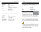
A maximum of 2 Transceivers can be connected together in one segment.
When two hubs are connected via Transceivers together, the same rule of cas-
cading two 100Mb hubs applies to them. To cascade another hub to these two
hubs (using RJ-45), a switch or repeater must be used.
The Distance Extender is a switched port. This means another 100Mb hub
can be cascaded (with RJ-45) to the hub that has a Distance Extender Module
installed. Two Distance Extender modules can be connected together only at
Half Duplex. Do NOT set either or both of the Distance Extender modules to
Full Duplex. The 10/100 Hubs will not communicate at Full Duplex.
11
Instant EtherFast II Series
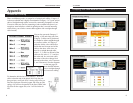
Follow these steps to install the add-on modules in the EtherFast II 10/100
Hub (EF2H16 or EF2H24).
1. Power off the hub and remove the AC power cord from the hub.
2. Remove all RJ-45 cables from the all the ports in the hub and if the hub is
on a rack remove the hub from the rack
3. Using a Phillips screw driver, remove the screws holding the small cover
panel on the back of the hub. The size of the panel is about 8.1cm by 3.5cm
(3.1" x 1.4"). You will need the screws to secure the add-on module later.
4. Ground yourself properly and remove the add-on module from its package.
5. Hold the module so the chips and the components on the add-on module
are facing up. If the module has a daughter board (a bigger board mounted on
the main board of the add-on module), the bottom of the daughter board
should be facing up. Insert the module into the back of the hub.
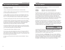
6. The add-on module will slide in until it comes to a stop. Push the module
to make sure it makes a proper connection. Note: Do not use too much force,
you can bend the metal panel on the add-on module.
7. Secure the module in place with the two screws.
8. If used on a rack, mount the hub back on the rack. Reconnect the RJ-45
cables and the AC Power cord. Note: do not connect any cables to the port(s)
that will be used by the add-on Module (see page 11 to find which ports can't
be used when using an add-on module).
9. Connect your Fiber cable or RJ-45 cable to the add-on Module. Turn on
the hub.
10
Fiber Optic ModulesHow to Install An Add-On Module
NNoottee::
The duplexing switch (located on the back of
the hub) should be set in
HHaallff DDuupplleexx
mode. The
10/100 Hubs do not function in full duplex mode.