


25
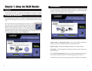
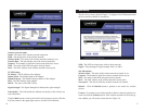
WEP (Disabled/64-bit WEP/128-bit WEP) - If you do not want to use
WEP encryption, choose Disabled. To use WEP encryption (recommended
to increase network security), select 64-bit or 128-bit WEP from the drop-
down menu, and enter either a Passphrase or WEP key.
Passphrase - Instead of manually entering WEP keys, you can enter a
Passphrase, so that a WEP key is automatically generated. It is case-sensi-
tive and should not be longer than 16 alphanumeric characters. This
passphrase must match the passphrase of your wireless network and is com-
patible with other Linksys wireless products only. (If you have any non-
Linksys wireless products, enter the WEP key(s) manually on those prod-
ucts.)
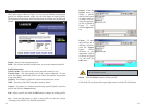
WEP Key - This WEP key must match the WEP key of your wireless net-
work. If you are using 64-bit WEP encryption, then the key must consist of
exactly ten hexadecimal characters. If you are using 128-bit WEP encryp-
tion, then the key must consist of exactly 26 hexadecimal characters. Valid
hexadecimal characters are “0” to “9” and “A” to “F”.
TX Key - This allows you to access different WEP keys used by different
routers or access points in your network. Choose the TX Key used in that
network. For instance, if the device uses TX Key 3, use TX Key 3. If you’re
not using multiple WEP Keys, leave this set at 1.
24
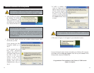
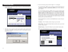
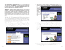
7. The Confirm New Settings screen will appear (shown in Figure 7-15). To
save the new settings, click the Ye s button. To cancel the settings and return
to the
Profiles
screen, click
the Cancel
button. To
edit the new
settings,
click the
Back but-
ton.
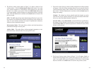
8. The Congratulations screen (Figure 7-16) will appear next. Click Activate
new settings now to implement the new settings immediately and return to
the Link Information screen. Click Activate new settings later to keep the
current settings active, and return to the Profiles screen so that you can edit
your profile
or create
another pro-
file.
You have successfully created a connection profile. Click the X (Close) but-
ton in the upper right corner to exit the WLAN Monitor.
Figure 7-15
Figure 7-16
Figure 7-14