Analog Telephone Adapter with 2 FXS Ports
List of Figures
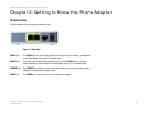
Figure 2-1: Back Panel . . . . . . . . . . . . . . . . . . . . . . . . . . . . . . . . . . . . . . . . . . . . 3
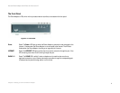
Figure 2-2: Front Panel . . . . . . . . . . . . . . . . . . . . . . . . . . . . . . . . . . . . . . . . . . . . 4
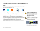
Figure 3-1: Connection Diagram of a Typical Setup . . . . . . . . . . . . . . . . . . . . . . 5
Figure 3-2: Connect the RJ-11 Telephone Cable. . . . . . . . . . . . . . . . . . . . . . . . . 5
Figure 3-3: Connect the Ethernet Network Cable . . . . . . . . . . . . . . . . . . . . . . . . 6
Figure 3-4: Connect the Power Adapter . . . . . . . . . . . . . . . . . . . . . . . . . . . . . . . 6


