


2-4 Installing the LSI20160
Copyright © 2001 by LSI Logic Corporation. All rights reserved.
2.2.3 Inserting the Host Adapter
Perform the following steps to install the LSI20160 in your PC mainboard.
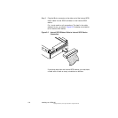
Step 1. Remove the blank bracket panel on the back of the computer
aligned with the PCI slot you intend to use.
Save the bracket screw.
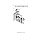
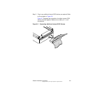
Step 2. Carefully insert the edge connector J1 of the host adapter into
the PCI slot.
Make sure the edge connector is properly aligned before
pressing the board into place. The bracket around connector J2
should fit where the blank bracket panel was removed. Refer to
Figures 2.1 and 2.2.
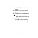
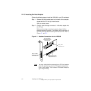
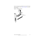
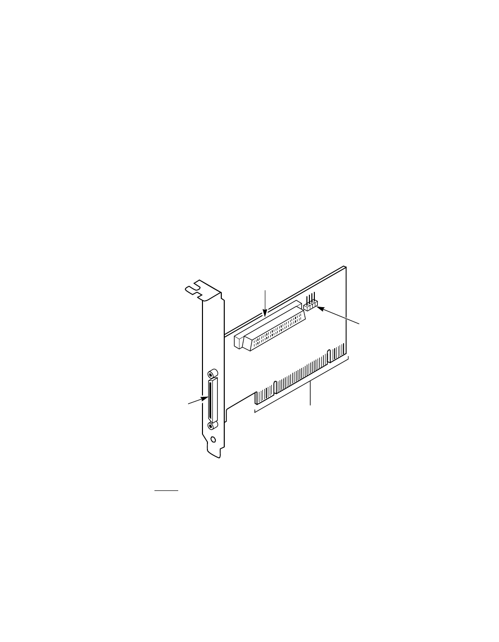
Figure 2.1 Hardware Connections for the LSI20160
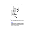
Note: You may notice that the components on a PCI host adapter
face the opposite way from non-PCI adapter boards you
have in your system. This is correct. The board is keyed to
go in only one way.
68-pin Internal
High Density SCSI
Connector J4
68-pin VHDCI
External SCSI
Connector J2
Busy LED
Connector J3
LSI20160 to PCI Bus
Edge Connector J1