


Physical Characteristics 2-17
Copyright © 2002 - 2005 by LSI Logic Corporation. All rights reserved.
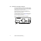
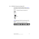
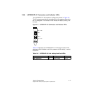
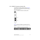
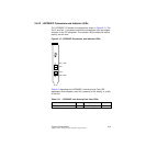
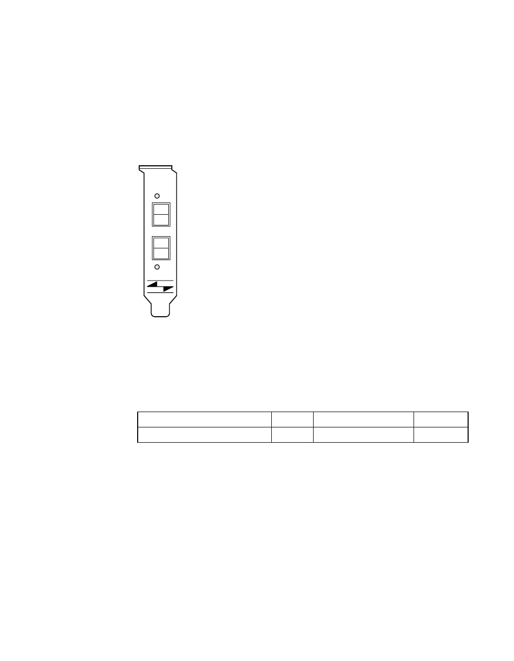
2.8.8 LSI7202LXP-LC Connectors and Indicator LEDs
The LSI7202LXP-LC I/O bracket is configured as shown in Figure 2.8.
The LC connectors provide the connections from the adapter channels to
the FC subsystem. The indicator LEDs indicate link status, activity, and
link fault.
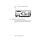
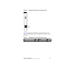
Figure 2.8 LSI7202LXP-LC Connectors and Indicator LEDs
Table 2.10 describes the LSI7202LXP-LC Link Activity/Link Fault LED
appearance that indicates a valid link, presence of link activity, or a fault
on the link.
Table 2.10 LSI7202LXP-LC Link Activity/Link Fault LEDs
Link Activity Fault
LED Appearance Off Green Blinking Yellow
Port 0
Port 0 LED
Port 1
Port 1 LED