


Detailed Installation Procedure 2-5
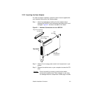
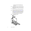
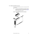
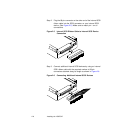
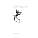
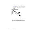
Step 7. The bracket around the connectors J3 (see Figure 2.1) should
fit in the slot where you removed the blank panel. Secure the
bracket with the bracket screw (see Figure 2.2) before making
the internal and external SCSI bus connections.
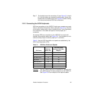
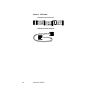
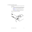
2.2.3 Connecting the SCSI Peripherals
SCSI bus connections to the LSI8751D inside your computer are made
with an unshielded, 68-conductor ribbon cable (see Figure 2.3). One side
of this cable is marked with a color to indicate the pin-1 side. Sometimes
the connectors on this cable are keyed to ensure proper pin-1
connection.
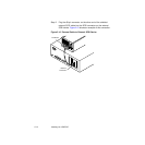
All external SCSI bus connections to the LSI8751D are made with
shielded, 68-conductor cables (see Figure 2.3). The connectors on this
cable are always keyed to ensure proper pin-1 connection.
Table 2.1 lists the SCSI bus widths and speeds as established by the
SCSI Trade Association (STA).
Important: Use only cables designed and specified for operation with
Ultra SCSI devices to make connections to the LSI8751D.
See Figure 2.3 for an example of the required cables.
Table 2.1 SCSI Bus Widths and Speeds
STA Terms
SCSI Bus
Width, Bits
SCSI Bus Speed
Maximum Data Rate,
Mbytes/s
SCSI-1 8 5
Fast SCSI 8 10
Fast Wide SCSI 16 20
Ultra SCSI 8 20
Wide Ultra SCSI 16 40
Ultra2 SCSI 8 40
Wide Ultra2 SCSI 16 80