


4
OPT•24
OPT•24
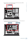
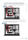
6) Unplug both ends of the COM cable (040-383-00), located between the front panel Display board (A)
and the Card Cage board (B). Cable ties hold the COM cable in place. Leave the cable inside the
HDR24/96 in case the OPT•24 is ever removed and the COM cable needs to be reconnected.
REAR PANEL
FRONT PANEL
REAR PANEL
®
MACKIE DESIGNS. ™
© 2000
6) Remove the COM Cable
from the Display Board (A)
and the Card Cage Board (B)
040-383-00
B
A
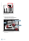
J3B J4B
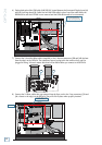
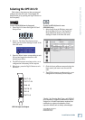
8) Connect the 2 ribbon cables that you removed from the Sync card to the 2 top connectors (J3A and
J4A, closest to the edge) on the OPT•24. They will click in place when properly inserted.
7) Connect the 2 short/fat ribbon cables (supplied) to the 2 bottom connectors (J3B and J4B, furthest
from the edge) on the OPT•24. The connectors have a keying tab in the center so they can’t be
plugged in wrong. It doesn’t matter which end of the ribbon cables you connect to the OPT•24.
REAR PANEL
FRONT PANEL
REAR PANEL
®
MACKIE DESIGNS. ™
© 2000
8) Connect 2 Ribbon Cables
to OPT¥24 Board
OPT¥24 Board