


SP400C – 6
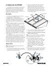
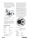
B6.Pull the speaker cable through the conduit
coupler and attach to the supplied Phoenix-type
connector (8). This is a 4-position connector,
with two "+" and two "–" terminals. Connect the
speaker cable to the "+" and "–" terminals labeled
IN. If connecting another speaker in a distributed
system (in parallel), connect the speaker cable
running to the next speaker to the "+" and "–"
terminals labeled LOOP THRU.
7. Specifications
System Acoustic
Frequency Range: 70 Hz–22 kHz (–10 dB)
Frequency Response: 89 Hz–20 kHz (–3 dB)
Sensitivity: 92 dB
Crossover Point: 2000 Hz
Power Handling: 120 watts peak
30 watts long term
Maximum SPL: 107 dB
Transformer Taps
70V: 3.75 W, 7.5 W, 15 W, 30 W
100V: 7.5 W, 15 W, 30 W
Operation in High-Pass Mode
Frequency Response: 150 Hz–20 kHz
Operation in Low-Impedance Mode
Frequency Response: 89 Hz–20 kHz
B7.Close the terminal cover plate (7) and tighten the
locking screw (7a) firmly.
B8.Insert the conduit into the coupler and fasten
with the set-screw.
Note: A seismic safety tab (10) is provided to
secure the loudspeaker to the building structure
with wire cabling for additional support where
required by local construction codes. We
recommend using this secondary support for
additional safety.
1234
+
L
O
O
P
T
H
R
U
L
O
O
P
T
H
R
U
I
NIN
+ ––
IN
+
IN
–
LOOP
THRU
–
LOOP
THRU
+
Conduit
Coupler
Set-Screw
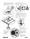
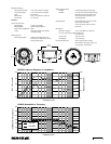
4. Set the Tap Selector Switch (12). Make sure all
the taps in the system add up to less than the
rated power of the amplifier driving them. As a
general rule, you should provide at least 10%
headroom to account for insertion losses (i.e.,
wiring resistance, etc.). For example, if you have
four speakers tapped at 30 watts each, the
amplifier should be rated at least 132 watts.
5. Set the Full-Range/High-Pass Selector Switch
(13). For normal operation, set the switch to the
FULL RANGE position. If a subwoofer is being
used in the system to reinforce the very-low
frequencies, use the HIGH PASS position to roll
off the frequencies below 150 Hz. This provides
the added benefit of making more power
available for the crucial mid and high frequencies.
If the speaker is being used in a low-impedance
system, use the FULL RANGE (16 OHM)
position. This bypasses the tapped transformer.
6. Install the grille (1) by pressing it into place until
the front of the grille is flush with the front baffle
rim. It is important that the grille be securely
seated to avoid having it vibrate loose.
Control Features
Front-mounted Rotary Switch:
Full Range (70/100 Volt Systems)
High Pass (70/100 Volt Systems)
Full Range (16 Ω)(Low-Impedance Systems)
Front-mounted Rotary Switch:
Secondary Tap Positions
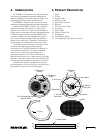
Transducers:
Low Frequency
Number of Drivers: 1
Woofer Size: 6.5" (165 mm)
Diaphragm Material: Polypropylene
Magnet Type: Ferrite
High Frequency:
Diaphragm Size: 1.0" (25 mm)
Diaphragm Material: Damped Cloth
Magnet Type: Neodymium Dome
3.7
7.5
15
30
70v
100v
HIGH
PAS S
FULL
RANGE
FULL
RANGE
(16 OHMS)
7.5
15
30