TimewARP 2600 Getting Started Guide
9
VCO 1
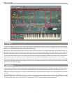
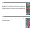
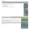
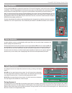
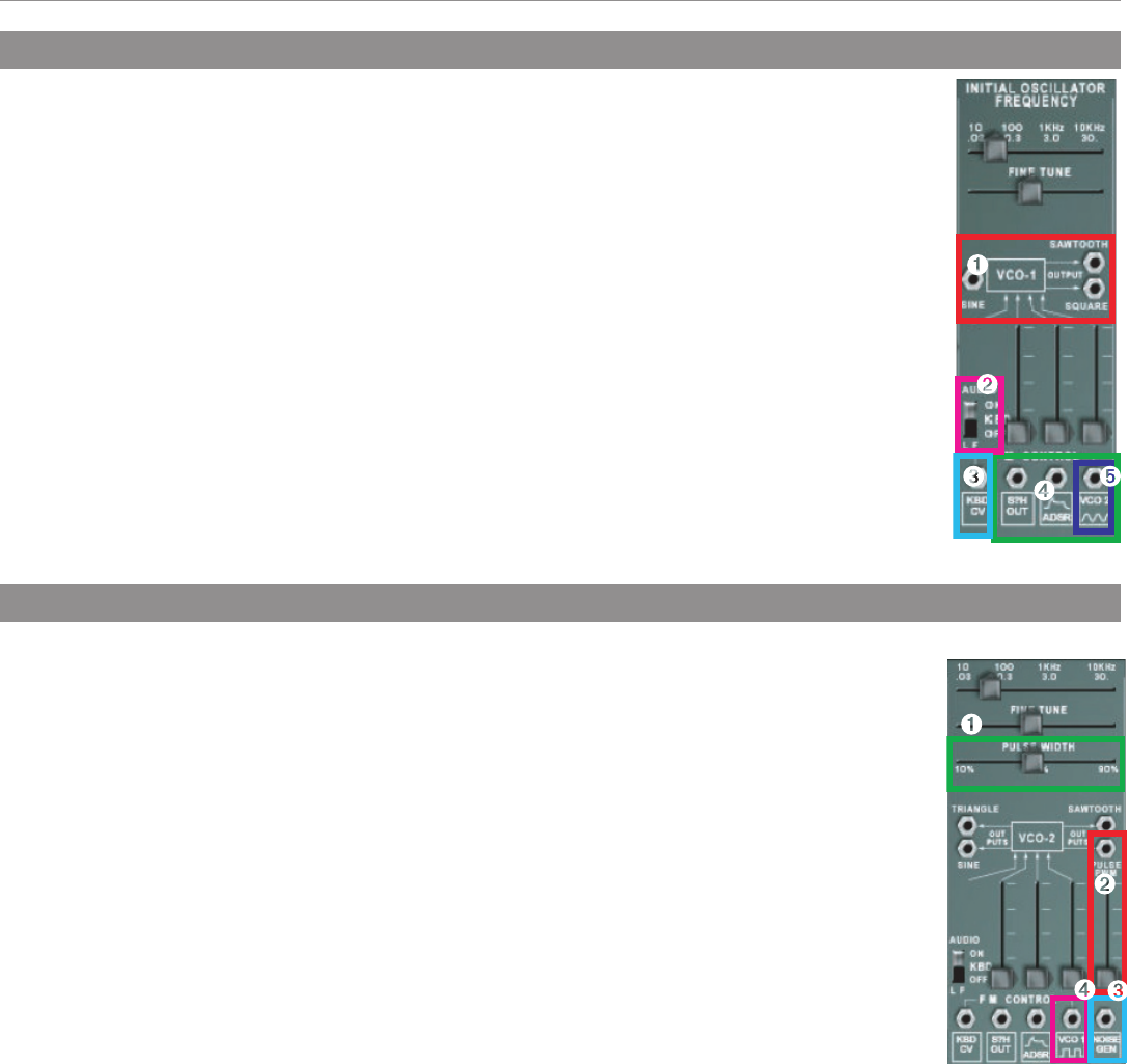
VCO 1 ➊ generates saw, square, and sine outputs.
The default signal to the first (unattenuated) FM Control input is from the keyboard. The Audio/LF switch
➋ above this input
switches the mode of the VCO from Audio (10Hz - 20,000Hz) to LFO Mode (0.03Hz – 30Hz).
When the VCO is in LFO Mode, the default connection to the keyboard is removed. This can be overridden in this mode by
patching a cable to the Keyboard CV output ➌ on the left side of the keyboard output on the left side of the front panel.
The default signals to the next three FM Control inputs are from a) the Sample & Hold, b) the ADSR Envelope Generator
➍ ,
and c) VCO2 sine ➎, which is the output from VCO2’s sine wave generator.
VCO 2
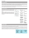
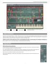
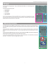
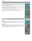
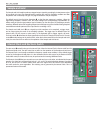
VCO 2 ➊ generates sine, triangle, sawtooth, and pulse outputs. A pulse-width slide control can adjust the duty cycle
from 10% to 90%; at the middle of its travel, the pulse width is 50% (a square wave). There is a fourth attenuator-governed
input ➋, for digital control of the pulse width. The default signal at this PWM input is from the Noise Generator ➌.
Just like VCO1, VCO2 has the same first three FM CONTROL inputs, and an additional one, VCO1 square, which is an input
from VCO1’s square wave generator
➍.


