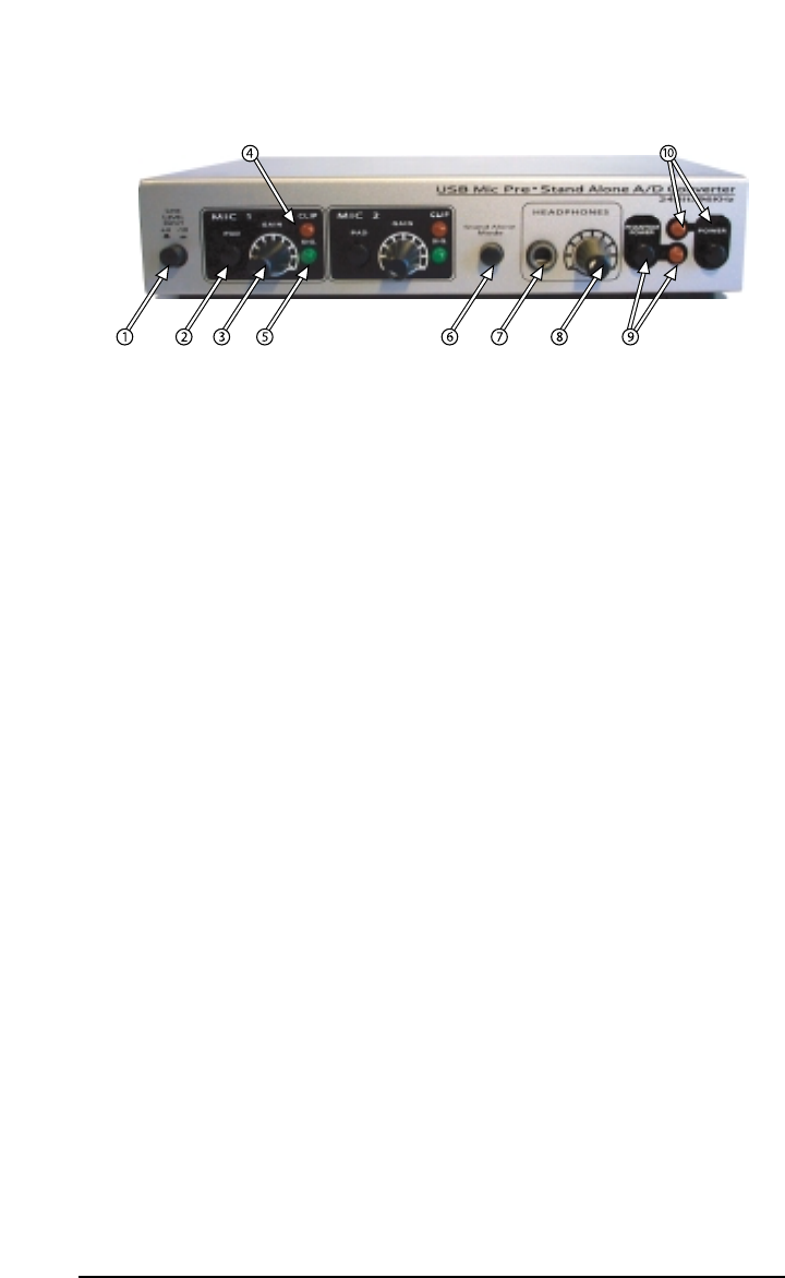
Front Panel:
1. Line Level Input Switch: This switch will set the input line level for the Duo.
With the switch in the out position, the Duo will operate at a +4dBu line level.
Pressing and locking this switch to the in position will set the operating line
level to -10dBV.
2. Pad Switch: One pad switch has been provided for each mic input on the Duo.
Pressing in and engaging the Pad switch will apply a 20dB pad, or “cut,” to
the microphone input prior to the microphone preamp.
3. Gain: This potentiometer controls the amount of gain applied to the
microphone preamp. One Gain pot is provided for each mic input.
4. Clip LED: This LED responds to the signal present at the Duo’s respective Mic
input, and will begin to light when the signal reaches clipping.
5. Sig. (Signal) LED: This LED responds to the signal present at the Duo’s
respective Mic input, and will begin to light when a nominal signal is present
at the input.
6. Standalone: Pressing in and engaging the Standalone switch will connect the
Mic and Line inputs directly to the analog Line Outs, S/PDIF output, and the
Headphone output. Standalone mode allows for use of the Duo as a mic
preamp and/or analog to digital converter independent of the computer. This
feature of the Duo also allows you to directly monitor the inputs when
connected to a computer.
7. Headphone Out Jack: This output jack is designed to connect to a 1/4” TRS
plug, typically for use with a set of stereo headphones. The source for the
signal at the Headphone Out is identical to the Line Outs.
8. Headphone Level: This knob controls the amount of monitoring level sent to
the Duo’s Headphone Out jack.
9. Phantom Power Switch & corresponding LED: Pressing in and engaging the
Phantom Power switch will send 48V of phantom power to the Duo’s Mic
inputs. When phantom power is switched on, the corresponding Phantom
Power LED will light and remain lit.
10. Power Switch & corresponding LED: Pressing in and engaging the Power
switch will power up the Duo, provided that the proper power supply is
connected to the 9V AC Power jack. When power is switched on, the
corresponding Power LED will light and remain lit.
4


