9
particular installation. If this equipment does cause harmful interference to radio or
television reception, which can be determined by turning the equipment off and on, the
user is encouraged to try to correct the interference by one or more of the following
measures:
• Reorient or relocate the receiving antenna
• Increase the separation between the equipment and the receiver
• Connect the equipment into an outlet on a circuit different from that to which the
receiver is connected
• Consult the dealer or an experienced radio / TV technician for help
Notice: Shielded cables, if any, must be used in order to comply with the emission limits.
Any change or modification not expressly approved by the Grantee of the equipment
authorization could void the user’s authority to operate the equipment.
Canadian DOC Compliance Statement
This equipment does not exceed Class B limits for radio noise emissions for a digital
apparatus, set out in the Radio Interference Regulations of the Canadian Department
of Communications. Operation in a residential area may cause unacceptable interfer-
ence to radio and TV reception requiring the owner or operator to take whatever steps
necessary to correct the interference.
Cet équipement ne dépasse pas les limits de Class B d'émission de bruits radioélectriques
pour les appareils numériques, telles que prescrites par le Règlement sur le brouillage
radioélectrique établi par le ministère des Communications du Canada. L'exploitation
faite en milieu résidentiel peut entraîner le propriétaire ou l'opérateur à prendre
dispositions nécessaires pour en éliminer les causes.
Disclaimer, Copyright, And Other Notices
The information contained in this manual has been validated at the time of this manual's
production. The manufacturer reserves the right to make any changes and improve-
ments in the product described in this manual at any time and without notice.
Consequently, the manufacturer assumes no liability for damages incurred directly or
indirectly from errors, omissions or discrepancies between the product and the manual.
All registered trademarks are the property of their respective owners.
Copyright © 1996 MaxTech. All rights reserved. No reproduction of this document in any
form is allowed without written permission from MaxTech.
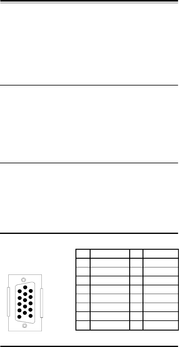
Appendix D - Video Cable Pinout
First Edition GZ/DR - Version 1.0
Figure E - Pin
Layout and Pin
Assignment Chart
6
1
5
10
11
15
PIN SIGNAL PIN SIGNAL
1 Red 9 No Connect
2 Green 10 Digital Ground
3 Blue 11 Ground
4 Ground 12 No Connect
5 Ground 13 Hor. Synch.
6 Red Ground 14 Vert. Synch
7 Green Ground 15 No Connect
8 Blue Ground


