


HOST SOFTWARE INTERFACE
6 – 1
SECTION 6
Host Software InterfaceHost Software Interface
Host Software InterfaceHost Software Interface
Host Software Interface
The host communicates with the drive through a set of controller registers accessed via the host’s I/O ports.
These registers divide into two groups: the Task File, used for passing commands and command parameters and
the Control/Diagnostic registers.
Task File RegistersTask File Registers
Task File RegistersTask File Registers
Task File Registers
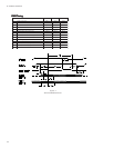
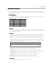
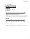
The Task File consists of eight registers used to control fixed disk operations. The host accesses each register
by the I/O port address shown in this Task File register map:
TROPO/IDAERETIRW
h0F1retsigeRataDretsigeRataD
h1F1retsigeRrorrEretsigeRserutaeF
h2F1tnuoCrotceStnuoCrotceS
h3F1rebmuNrotceSrebmuNrotceS
h4F1woLrednilyCwoLrednilyC
h5F1hgiHrednilyChgiHrednilyC
h6F1)HDS(daeH/evirD)HDS(daeH/evirD
h7F1retsigeRsutatSretsigeRdnammoC
Data RegisterData Register
Data RegisterData Register
Data Register
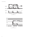
Provides access to the drive’s sector buffer for read and write operations. With the exception of ECC byte
transfers (which, during Read long and Write long commands, are 8 bits wide), data transfers through the
Data register are all 16 bits wide.
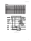
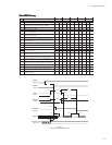
Error RegisterError Register
Error RegisterError Register
Error Register
A read-only register containing specific information regarding the previous command. Data interpretation
differs depending on whether the controller is in operational or diagnostic mode. A power up, reset,
software reset, or receipt of a diagnostic command sets the controller into diagnostic mode. This mode
invalidates contents of the Status register. The contents of the Error register reflect a completion code.
Issuing any command (apart from a Diagnostic command) places the controller into operational mode.
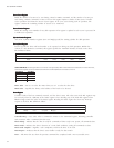
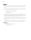
In operational mode, the Error register is valid only when the Error bit in the Status register is set. The bit
definitions for operational mode follow:
76543210
0CCE0 FNDI0TRBA0KTFNMA
ecafretnI
CRC
ataD
rorrECCE
toN
desU
DI
dnuoFtoN
toN
desU
detrobA
dnammoC
0kcarT
rorrE
sserddA
toNkraM
dnuoF
Interface CRC – An interface CRC error occurred during an Ultra DMA transfer.
Data ECC Error – An non-correctable ECC error occurred during a Read Sector command.
Firmware Problem – Indicates a firmware problem was detected, (e.g., invalid interrupt, divide overflow).
ID Not Found – Either a matching ID field not found, or a CRC error occurred.
Aborted Command – Invalid commands, write fault, no seek complete, or drive not ready.
Track 0 Error – Track 0 was not found during execution of a Restore command.
Address Mark Not Found – The Address Mark could not be found after an ID match.
Features RegisterFeatures Register
Features RegisterFeatures Register
Features Register
Enables or disables features through the Set Features command.