


NumaLink-3.0™ Users Guide and Service Manual
Page 19 of 33
5. Technical Support
5.1 Logging and Error Reporting
NumaLink-3.0 logs messages that indicate the progress of translations; these messages can also help in
understanding and resolving translation problems.
You can see the messages in two ways:
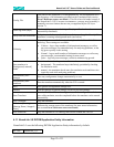
1. Messages from the current translation session are shown in the Status tab of the NumaLink-3.0 GUI;
see section 4.3.
2. Messages from all sessions are appended into log files that, by default, are stored in
C:\Program Files\Numa\Logs
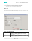
The full paths to the log files are displayed in the General tab of the NumaLink-3.0 GUI, as shown in
section 4.1.
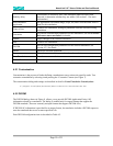
The verbosity of these messages is configurable, also on the General tab. We recommend the Normal
setting for most situations; if you are reporting a translation error to the Numa Technical Support Staff,
you may be asked to rerun the translation with the Verbose message setting.
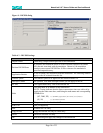
5.2 Remote Diagnostics
NumaLink-3.0 translation systems come with remote diagnostics software pre-installed and configured.
This software, called pcAnywhere, allows the Numa Technical Support Staff to dial in to the
NumaLink system for troubleshooting and software upgrades.
NOTE In order to receive remote support, the NumaLink-3.0 system must be connected to a
dedicated analog phone line that does not run through a PBX phone system. This is also called a
D.I.D. (Direct In-Dial) line. If you have to dial a number (such as 9) to get an outside line, then the line is
not a D.I.D. line. Digital (PBX) phone lines such as those in hospitals will damage the modem, so please
double-check with the personnel in charge of the phone system at your site.
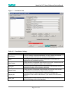
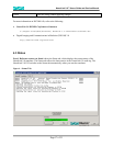
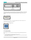
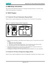
When attaching the phone line to the back of the NumaLink-3.0 computer, please make sure that it is
plugged into the appropriate jack. The modem will have two jacks side by side; plug the phone line into
the one labeled “TELCO” (it may instead have a picture of the plastic connector for the line); see Figure
10.
Figure 10 – Proper Telephone Line Connection