PCI-QUAD-AC5 User's Guide Installing the PCI-QUAD-AC5
Field wiring and signal termination
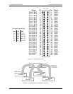
You can use the following screw terminal boards to terminate field signals and route them into the PCI-
QUAD-AC5 using the C50FF-x cable.
CIO-MINI50 – 50-pin universal screw terminal board. Four boards are required. Details on this
product are available on our web site at
www.mccdaq.com/cbicatalog/cbiproduct.asp?dept_id=102&pf_id=258
.
CIO-SPADE50 — 16" x 4" termination panel which mates with both 37-pin and 50-pin connectors.
Four boards are required. Details on this product are available on our web site at
www.mccdaq.com/pdfs/screw.pdf
.
CIO-TERM100 – 100-pin screw terminal board (daisy-chained 50-pin IDC connectors). Two boards
are required. Details on this product are available on our web site at
www.mccdaq.com/cbicatalog/cbiproduct.asp?dept_id=102&pf_id=281
.
SCB-50 – 50 conductor, shielded signal connection/screw terminal box provides two independent
50-pin connections. Two boards are required. Details on this product are available on our web site at
www.mccdaq.com/cbicatalog/cbiproduct.asp?dept_id=196&pf_id=1168
.
You can use the following relay mounting rack with the C50FE-x cable to provide digital signal
conditioning.
SSR-PB24 – 24 channel solid-state relay mounting and interface rack. Details on this product are
available on our web site at www.mccdaq.com/cbicatalog/cbiproduct.asp?dept_id=122&pf_id=619
.
The PCI-QUAD-AC5 supports up to four SSR-PB24 boards (one cable required per SSR-PB24).
2-6


