


700 Elmont Rd, Elmont, NY 11003, Tel: 516-285-1000; Fax: 516-285-6300
www.Meridian-tech.com
Page 7 3/07 Rev 1.2
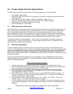
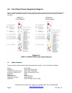
4.0 Front Panel Pinout Assignment Diagram
Figure 4.1 below shows the front panel layout, connector location, indicator location and pinout assignment for
both the RGB-T and RGB-R modules. This diagram shows the video pinouts for the on-board DVI-I video
connector.
Figure 4.1
RGB-T-0 & RGB-R-0 Front Panel Layout Diagrams
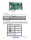
4.1 Status Indicators
There are function status indicator lights associated these modules. They are identified as follows:
Power: Green (ON)
Diagnostic: Green (OK), Red (alarm)
Tx Carrier (transmitter only): Green (OK), Red (alarm)
Rx Carrier (receiver only): Green (Present)/Red (Error)
DVI active: Green
RGB active: Green
SHV (sync H&V): Green (present)
SOG (sync on green): Green (present)
USB active: Green (Rx-data), Red (Tx-data)
RGB/DVI-T RGB/DVI-R
Pinout Diagram Pinout Diagram