


66
SCANNER AND CABLE TERMINATIONS
SCANNER PINOUT CONNECTIONS
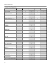
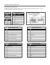
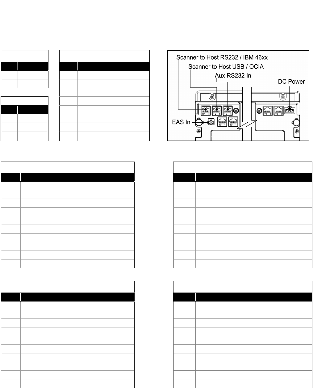
The MS2220 Series scanner interfaces terminate to 10-pin modular jacks located on the bottom of the units. The serial
number label indicates the model number of the scanner.
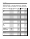
EAS In
Auxiliary RS232 In
Pin Function
Pin Function
1 EAS In
1 Ground
2 EAS Out
2 RS232 Receive Input
3 RS232 Transmit Output
DC Power In
4 RS232 RTS In
Pin Function
5 RS232 CTS Out
1 12VDC
6-8
No Connect
2 Ground
9 +5V Out
3 5.2VDC
10
No Connect
Figure 63. Connector Layout
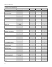
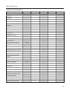
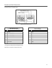
Scanner IBM 46xx to Host
Scanner RS232 to Host
Pin Function Pin Function
1 Signal Ground 1 Ground
2
Reserved for RS232 Interface
2 RS232 Transmit
3
Reserved for RS232 Interface
3 RS232 Receive
4
Reserved for RS232 Interface
4 RS232 RTS
5
Reserved for RS232 Interface
5 RS232 CTS
6
Reserved for RS232 Interface
6 RS232 DTR
7
No Connect
7
No Connect
8
Reserved for RS232 Interface
8 DSR
9 IBM B- 9
Reserved for IBM 46xx Interface
10 IBM A+ 10
Reserved for IBM 46xx Interface
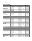
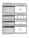
Scanner OCIA to Host
Scanner USB to Host
Pin Function Pin Function
1 Signal Ground 1 Signal Ground
2 OCIA R Data 2
Reserved for OCIA Interface
3 OCIA Clock In 3
Reserved for OCIA Interface
4 Shield Ground 4 Shield
5 OCIA Clock Out 5
Reserved for OCIA Interface
6 OCIA Clock In Return / Clock Out Return 6
Reserved for OCIA Interface
7
Reserved for USB Interface
7 PC +5VDC
8 OCIA R Data Return 8
Reserved for OCIA Interface
9
Reserved for USB Interface
9 Data -
10
Reserved for USB Interface
10 Data +
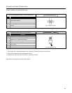
Specifications are subject to change without notice.