


40
SCANNER AND CABLE TERMINATIONS
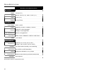
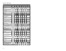
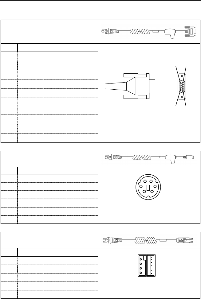
Cable Connector Configurations (Host End)
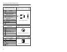
“Standard” PowerLink Cable
53-53xxx coiled or 54-54xxx straight
Pin Function
1 Shield Ground
2 RS232 Transmit Output
3 RS232 Receive Input
4 DTR Input/Light Pen Source
5 Power/Signal Ground
6
Light Pen Data
(DSR Out for -14 interfaces)
7
CTS Input
8 RTS Output
9+5VDC
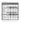
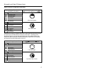
Stand Alone Keyboard PowerLink
Cable
53-53020
Pin Function
1 PC Data
2NC
3 Power Ground
4 +5VDC PC Power to KB
5 PC Clock
6NC
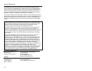
USB Power/Communication Cable
53-53213 or 53-530214
Pin Function
1 PC +5V/V_USB
2D-
3D+
4 Ground
Shield Shield
9
-
Pin D
-
Type Connector
95
61
4
21
3
65
6-Pin Male Mini-DIN Connecto
r
USB Type A Locking with Power
1
4