


3400723200/AC - Page 5
Contents
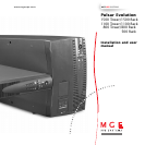
1. Presentation
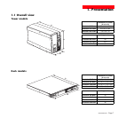
1.1 Overall view.................................................................................................................................. 7
Tower models ..................................................................................................................................7
Rack models ....................................................................................................................................7
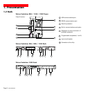
1.2 Back .............................................................................................................................................. 8
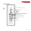
1.3 Control panel..................................................................................................................................9
2. Installation
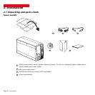
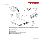
2.1 Unpacking and parts check ......................................................................................................10
Tower models ................................................................................................................................10
Rack models ..................................................................................................................................11
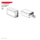
2.2 Installation ....................................................................................................................................12
Tower models ................................................................................................................................12
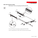
800/1100/1500 Rack models..........................................................................................................13
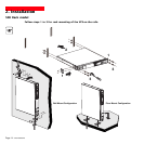
500 Rack model ............................................................................................................................14
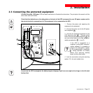
2.3 Connecting the protected equipment ........................................................................................15
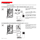
2.4 Connection to the RS232 or USB communications port (optional) ........................................16
2.5 Connection to the data-line protection port (optional)..............................................................16
2.6 Installation of the communications-card option ......................................................................17
3. Operation
3.1 Start-up..........................................................................................................................................18
3.2 Shift to booster or fader mode (during voltage variations in the AC-input power) ....................18
3.3 Operation on battery power (following failure of AC-input power) ............................................19
Transfer to battery power ..............................................................................................................19
Threshold for the low-battery warning............................................................................................19
3.4 Personalization (optional) ............................................................................................................20
Function..........................................................................................................................................20
ON / OFF conditions tab ................................................................................................................20
Battery tab......................................................................................................................................20
Voltage-thresholds tab ..................................................................................................................21
Sensitivity tab ................................................................................................................................21