


Page 4 - 51033211EN/AC
Contents
1. Presentation
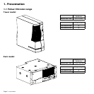
1.1 Pulsar EXtreme range................................................................................................................. 7
Tower model.................................................................................................................................... 7
Rack model ..................................................................................................................................... 7
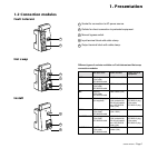
1.2 Connection modules ................................................................................................................... 8
Fault tolerant ................................................................................................................................... 8
Hot swap ......................................................................................................................................... 8
Install............................................................................................................................................... 8
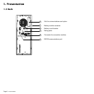
1.3 Back ............................................................................................................................................. 9
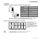
1.4 Options .......................................................................................................................................... 9
Transformer for galvanic isolation or earthing arrangement change .............................................. 9
Battery extensions for UPS backup times of 66 minutes ................................................................ 9
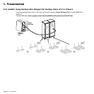
CLA module (Long backup time charger) for backup times of 2 to 8 hours .................................. 10
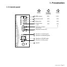
1.5 Control panel ............................................................................................................................... 10
2. Installation
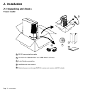
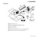
2.1 Unpacking and checks ............................................................................................................... 12
"Tower" model ............................................................................................................................... 12
"Rack" model ................................................................................................................................ 13
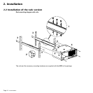
2.2 Installation of the rack version .................................................................................................. 14
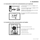
2.3 Connection to the RS 232 communications port (optional) ................................................... 15
2.4 Installation of the communications-card option ...................................................................... 15
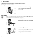
2.5 Securing and connecting the connection modules................................................................. 16
Securing the connection modules .................................................................................................16
Fault tolerant ................................................................................................................................. 16
Hot swap ....................................................................................................................................... 17
Install............................................................................................................................................. 18
3. Operation
3.1 ON-LINE operating mode ........................................................................................................... 19
3.2 Start-up ........................................................................................................................................ 20
3.3 Bargraph indications .................................................................................................................. 20